Advertisement
Quick Links
Pack 01
B U I L D
I N S T R U C T I O N S
STAGE 01: GRILLE AND HOOD
STAGE 02: FRONT LEFT WHEEL
STAGE 03: INSTRUMENT PANEL
STAGE 04: LEFT ENGINE BLOCK
"MERCEDES-BENZ" and
are the intellectual property of Mercedes-Benz Group AG.
They are used by Agora Models under license.
Advertisement

Subscribe to Our Youtube Channel
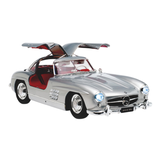
Summary of Contents for Agora Models Mercedes 300SL Gullwing 1955
- Page 1 I N S T R U C T I O N S STAGE 01: GRILLE AND HOOD STAGE 02: FRONT LEFT WHEEL STAGE 03: INSTRUMENT PANEL STAGE 04: LEFT ENGINE BLOCK "MERCEDES-BENZ" and are the intellectual property of Mercedes-Benz Group AG. They are used by Agora Models under license.
- Page 2 Advice from the experts Spare screws are included with each part. Occasionally, you may be instructed to keep spare or unused screws for a later stage. Keep these spares in a safe place and label them correctly. Please make sure you don’t mix up the screws. They look quite similar, but the threads do vary slightly. Using the wrong screws may damage the parts.
-
Page 3: Color Coding
STAGE 1: GRILLE AND HOOD COLOR CODING Start building the model by assembling the radiator grille The color coding of the parts shows and preparing the hood for assembly. how they should fit together. indicates STAGE 1 – REQUIRED PARTS screws and the right position. - Page 4 POSITIONING THE SUPPORT ROD Engine hood Support rod Slide the support rod through one of the holes on the edge of the hood , then gently push it through both rings in the supports (fig. 1) until it reaches the hole on the opposite side (fig.
- Page 5 STAGE 2: FRONT LEFT WHEEL In this stage, you will fit the tire onto the rim of the front left wheel and its brake drum. STAGE 2 – REQUIRED PARTS Code Name Quantity Material Front left tire Front left rim Zinc Brake drum Support plate...
- Page 6 PREPARING THE TIRE Front left tire The front left tire is difficult to bend at room temperature, and it is hard to press onto the rim. We recommend placing it in a container of hot water (approx. 170°F/75°C) for a few minutes.
-
Page 7: Instrument Panel
STAGE 3: INSTRUMENT PANEL In this stage, you will assemble your 300 SL’s dashboard, which includes the fuel and oil pressure gauges, along with the levers and switches for the air conditioning. You’ll also place the discs for the speedometer and tachometer, as well as the steering wheel with its column. - Page 8 ASSEMBLING THE DECORATIVE PANEL PART 1 Dashboard Place the decorative panel of the dashboard onto Decorative panel the instrument panel positioning the five trunnions of the panel to match the holes in the dashboard. ASSEMBLING THE DECORATIVE PANEL PART 2 Dashboard Decorative panel Caution!
- Page 9 STAGE 4: LEFT ENGINE BLOCK STAGE 4 – REQUIRED PARTS In this stage, you will assemble the first parts of the engine, and you will also join the fuel Code Name Quantity Material injection pump and the injection pipes to the left engine block.
- Page 10 FITTING THE FUEL PUMP Fuel injection pump Place the fuel pump onto the side of the injection pump , inserting the small guide peg into the indicated hole. Screw the injection pump to the left engine block with an MP screw. Guide peg Fuel pump FITTING THE FUEL INJECTION PUMP...
- Page 11 FITTING THE SUPPORT Insert the support into the hole provided for it on the upper left side of the left engine block . Screw the part in place with an MP screw. Left engine block Support FITTING THE INJECTION PUMP LINKAGE Insert the wide end of the injection pump linkage Injection pump linkage into the center hole of the bearing support...
- Page 12 FITTING THE FLYWHEEL COVER Position the flywheel cover Left engine block onto the base of the front part of the left engine block , making sure the small pin at the bottom is located in the correct hole as shown. Fix the cover in place with an MP screw.


Need help?
Do you have a question about the Mercedes 300SL Gullwing 1955 and is the answer not in the manual?
Questions and answers