Table of Contents
Advertisement
Advertisement
Table of Contents

Subscribe to Our Youtube Channel
Related Manuals for Jensen A 518 Di


Summary of Contents for Jensen A 518 Di
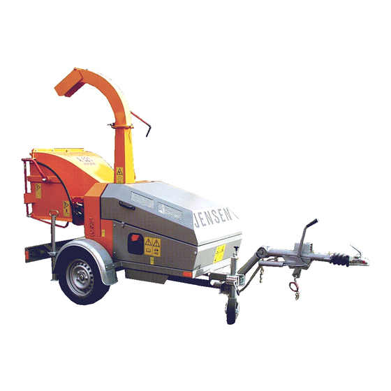
- Page 1 List of spare parts Machine : Woodchipper „Angeln“ Type : A518 DiXL D-905 E 80km/h v Machine No.: 5403011170 Date of building : 01/2003 Jensen Service Maasbüll GmbH D – 24975 Maasbüll Tel.: 04634 / 9370-0 Fax: 04634 / 1025 E-mail: jensenservicegmbh@t-online.de...
- Page 2 Before attempting any maintenance on the machines, read the instruction and safety manuel thouroughly. Jensen Service We are always striving to improve our product and we reserve the right to bring about any changes and improvements which we consider to be appropriate.
- Page 3 At the side of the instruction manual, on the application and on the insert there are binding regulations concerning accident prevention and the recognised technical rules for safety which must be complyed with. We wish you much success with the use of our machine in your work. Jensen Service.
- Page 4 (wood chipper) déclare que la machine (broyeur de branches) Typ/type/type : A 518 Di Seriennummer/serial number/numéro de série : 55403011170 den wesentlichen Sicherheits- und Gesundheitsschutz Anforderungen entspricht, gemäss der Bestimmung 89/392/EWG, und nachfolgenden Änderungen 91/368/EWG – 93/44/EWG –...
- Page 5 Bedeutung der Piktogramme Meaning of the pictograms Signification des pictogrammes Betekenis van de pictogrammen Piktogramme Bedeutung Position Pictogramm Meaning Place Pictogramme / Pictogrammen Signification / Betekenis Positionnement / Positie Vor Inbetriebnahme die Betriebs- anleitung und Sicherheitshinweise lesen und beachten. Service - Center Carefully read operator’s manual before Service - Center handling the machine.
- Page 6 Bedeutung der Piktogramme Meaning of the Pictograms Signification des pictogrammes Betekenis van de pictogrammen Piktogramme Bedeutung Position Pictogram Meaning Place Pictogramme / Pictogrammen Signification / Betekenis Positionnement / Positie Gefahr durch sich drehende Maschinen- teile. Alle Maschinen je 1x Keep away from rotating machine parts. rechts u.
- Page 7 Bedeutung der Piktogramme Meaning of the pictograms Signification des pictogrammes Betekenis van de pictogrammen Piktogramme Bedeutung Position Pictogram Meaning Place Pictogramme / Pictogrammen Signification / Betekenis Positionnement / Positie Gefahr durch fort schleudernde Teile bei laufendem Motor – Sicherheitsabstand halten. Trog rechts Danger –...
- Page 8 Bedeutung der Piktogramme Meaning of the pictograms Signification des pictogrammes Betekenis van de pictogrammen Piktogramme Bedeutung Position Pictogram Meaning Place Pictogramme / Pictogrammen Signification / Betekenis Positionnement / Positie Schaltstellungen Stop – Einzug - Rückwärts Switch position Stop – Input – backwarts Trog rechts Right side from infeed chute Positionnement du commutateur...
- Page 9 GENERAL SAFETY AND ACCIDENT PREVENTION INSTRUCTIONS With variations in machines, some of these statements may be contradictory as regards the servicing. In these cases it is advisable to follow the standard guidelines! Basic rules: Before anyone starts up the wood chipper study the safety rules for commerce and operation! Pay attention to the references in this operations guide as they are general legal safety and accident prevention instructions.
-
Page 10: Starting Instructions
On transport routes take precautionary safety measures to ensure that revolving pieces of equipment do not dangerously alter the area! Ensure that construction equipment/personnel are standing in a safe place! Additional weights In the construction of the Wood chipper, back and front propulsion is always sufficient for the load at the front and back respectively. - Page 11 Pay attention to the sliding clutch in the Cardan shaft and ensure that it is fully covered by the safety feature (machine and tractor) The covering of the safety features must be at least 50mm in total! Before turning on the PTO make sure that its high rotation speed power of the propulsion machine is equal to the permissible rotation speed of the Wood chipper! Before turning on the PTO take care that no one is in close enough proximity...
-
Page 12: Electrical Construction
After the process of tipping the container lower it co mpletely. When it is elevated, do not leave it unsupervised! You must drive only when the containers are lowered! Conditioning, attendance and repairs When carrying out repairs the machine must not be in motion. Check the breaks and the under wedge and remove the keys to the machine! After turning off the propulsion, the wood reducer can continue to rotate. -
Page 13: Wheels, Tyres
Take care when moving with battery fluids as they are corrosive! Use only th e prescribed fuses. If any stronger than these are used then the electrical structure will be destroyed resulting in the risk of fire! Always administer the plus terminal with a covering. If all are turned off at once there is a risk of explosion! Hydraulic construction. - Page 14 General work safety references. The wood chipper is built to the very highest standards of engineering and is totally reliable. Despite this however, this product can also be dangerous when it is not operated according to the instructions. Every person who handles the fitting, works on, and tests the wood chipper, must have read and understood the entire instruction manual.
-
Page 15: Important Safety Precautions
The Jensen Woodchipper is designed for reducing shrubs, bushes, branches, orchard and vineyard prunings etc., of unlimited length. The machine is for mounting an a tractor 3- point linkage and may also be supplied on a single or twin axle chassis for trailed use. - Page 16 Suitable clothing Always wear - Safety helmet with face visor Ear defenders Thick gloves (Avoiding tight fitting gloves) Overalls Avoid Loose clothing Ties Anoraks with loose cords Starting the machine Always start with the feed rollers disengaged (‚stop‘ position). Start the tractor, and engage the PTO, building up to 540rpm gradually. When the tractor is running at 540rpm, engage the feed rollers by pulling lever to ‚forward‘...
-
Page 17: Service Procedure
A425 / A328 / A325 = 35 Litres / minute A521 / A528 / A518 = 20 Litres / minute Greasing insructions Wood chipper Jensen – Lubricate spur gear teeth Aral 'SINIT III' – Lubricate UJ's and feed roller bearings with Shell 'RETINAX A'... - Page 18 Chipping length - Both rotor shaft bearings are grease filled for life (in normal working conditions) with Lithium grease including anti corrosive and anti penetration properties (Class 3). These bearings must not be re-greased or their working life will be significantly reduced.
- Page 19 Knife grinding overview with wear limit...
- Page 20 Hydraulic capacity regulator = 5 up to 20mm (larger pieces on request). Attention: Use only spare parts origine JENSEN. No warranty in case of using other products. In case of spare part order always mention the number of this machine.
- Page 21 A 425 Di A 425 Z A 521 / A528 Di 108 A 521 / A528 Z 108 A 518 Di A 518 Z Measurements taken at Maasbüll factory october 1990 in accordance with professional associations. Measuring point „M“ shown below.
- Page 22 Greasing Insructions A141, A231, A328, A325, A425 In order to maintain spur gears the grease type RETINAX G (Schell) is to be used. Use it to lubricate teeth of spur gears. A521, A518 In order to maintain spur gears the grease type ARAL SINIT III is to be used. Use it to lubricate teeth of spur gears.
- Page 23 Bushing Taper Lock Mount the pulley Make sure that all Put the pulley on the surfaces are clean and shaft, push it to the free from grease. Put correct position and the kone into the pulley fasten the screws tight and rotate to match the and even.
- Page 24 Joint Clean PTO shaft. Operate quick- Connecting Actuate locking disconnect lock. Pull on the PTO drive or push depending shaft. on lock model. For excessive Wide-angle CV PTO Joint articulations, drive shaft articulation stop PTO shaft. Check joint articulation in operation and standstill 1.
- Page 25 Joint Dismantling Remove retaining ring. Place joint as shown above and use light hammer blows to drive up bearing bush. As a function of size, fix bearing bush into spezial tool SW23 or SW27 and remove bearing bush by light hammer blows onto the yoke or by rotating it.
-
Page 26: Technical Data
Technical Data A518 Di transportation axle for 80 km/h Coupling Typ: BDRK 800 max. Weight: 750 kg Axle Knott VG /L Axle Load: 750kg Wheel: 155/80 R 13 Rim: 4 1/2"x13 H2 Air pressure: 2,5 bar Diesel engine 2 S 8870 Type: D - 905 Power:... -
Page 27: General Instructions
Service instructions for the axles. General instructions The fitting and installation instructions are part of the guarentee-service. Please understand that any welding and changes are not covered by the guarentee. Maintenance plan for the axles After the first use: Tighten the wheel nuts Check the wheel hubs After 50 working hours: Check the running of the wheel hubs... - Page 28 Automatic overload regulator Accessories Rotational speed display for service and operation. You can connect an external display on the terminal block X4 to display the actual rotational speed. Technical Data Nominal voltage From 12V DC – or 24V DC – on-board system with diesel generator set running.
-
Page 29: Operation
Automatic overload regulator Mounting of the pulse pick-up: For optimum functioning the following mounting dimensions should be adhered to: max. 2mm Setting must always be greater than D Operation Check the safe functioning of the unit. If operation is correct no special measures need to be taken nor any measures for maintenance an upkeep. - Page 31 Hydraulic circuit A518 DiXL fig. nr.: order nr.: designation pcs. 19300 hydraulik motor Bucher RF 99 29 08 0 A1 100ccm 1 19176 valve Bucher HDS 11 19172 hydraulik filter 19182 cartridge for filter 19054 hydraulik pump GPO 64 9689 tube 12 R/RL 2000 9880 tube 18 R/RL 750...
- Page 32 Engine drive A518 DiXL fig. nr.: order nr.: designation pcs. 5071 fitting key 12x8x40 9374 pulley 2x17x125 9322 shaft X 27.012.3 plate for clutch E 4.09 5336 washer A12 5402 bolt M12x35 2219 pulley 2x17x315 17059 v-belt 17x1460 Li 9130 bolt M10x1,25x25 9122 washer S10...
- Page 33 principal shaft / 2 knives disc A518 04.04.02 principal_shaft_2...
- Page 34 principal shaft / 2 knives disc A518 fig. nr.: order nr. designation pcs. 9177 principal shaft X4.43.1 9003 bearing UC210 9002 flage bearing UCPW210 9157 washer Ø41x5,4 DIN 7349 6120 washer A16 DIN 127 3024 screw M16x40 9260 bushing X47.001.1 22080 thread pen M16x35 DIN 914 1998...
- Page 35 retaction rollrews A518 fig. no. order no. designation pcs. 9279 spur gear Z23 M5 nylon MS5.23.30.04 9112 bushing Ø30/40x21 2125 springring A30 9146 shaft X7.5.1 9205 spur gear Z23 M5 X7.1.1 9030 collar 30 3084 fitting key 8x7x30 9021 flange bearing ASPFL 206 9206 spur gear Z12 M5 X7.19.1 9015...
- Page 36 A518 upper roller drive Fig. Nr.: Order Nr.: Designation pcs. 9112 bushing 30/40x21 X 7.9.1 9279 spur gear z23, m5 MS 5.23.30.04 9080X washer Ø13x1 2125 spring ring 9017 fitting key A8x7x35 2074 strain pin Ø8x45 9299 upper shaft X 57.005.1 9030 collar 9379...
- Page 37 A518 Lower retraction roller drive Fig.- Nr.: Order Nr.: Designation pcs. 9205 spur gear z23, m5 X 7.1.1 3084 fitting key A8x7x30 9030 collar 9020 lower roller X 5.5 screw M10x25 9203 shaft X 7.3.2 9021 flange bearing incl. Fig. 8 ASPFL 208 9022 bearing in Fig.
- Page 38 Auswerfer Ejector Goulotte d'éjection Die mit einem "+" gekennzeichneten Teile sind nicht abgebildet! Parts marked "+" are not shown in figures! Les positons précédées du signe "+" ne sont pas représentées!
- Page 39 Auswerfer Ejector Goulotte d'éjection Pos. Nr.: Bestell Nr.: Bezeichnung Designation Designation Anzahl Fig. Nr.: Order Nr.: pcs. Fig. Nr.: Ordre Nr.: pcs. 9060 Auswerfer kpl. ejector cpl. Goulotte d'éjection compléte 16535 Auswurfklappe adjustable trab clapet articulé 16234 Schraube screw 9240 Scheibe washer rondelle...
Need help?
Do you have a question about the A 518 Di and is the answer not in the manual?
Questions and answers