
Related Manuals for Jensen A530


Summary of Contents for Jensen A530
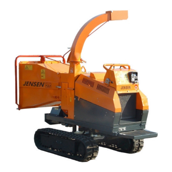
- Page 1 WOODCHIPPER Operating instructions List of spare parts Type : A530 DiXL D-1703 Track with tiltbed Machine Nr.: 5507062275 Date of building : 06/2007 Jensen Service GmbH D- 24975 Maasbüll Tel.: 04634 / 9370-0 Fax: 04634 / 1025 E-mail: info@jensen-service.de...
- Page 3 Before attempting any maintenance on the machines, read the instruction and safety manuel thouroughly. We are always striving to improve our product and we reserve the right to bring about any changes and improvements which we consider to be appropriate. An obligation to any previously delivered machines and extended apparatus is ínvalid.
- Page 4 At the side of the instruction manual, on the application and on the insert there are binding regulations concerning accident prevention and the recognised technical rules for safety which must be complyed with. We wish you much success with the use of our machine in your work. Jensen Service.
- Page 5 (stamp / cachet) Datum Unterschrift (date) (signature) Vertrieb über: (distributed by / distribué par:) Jensen Holzhackmaschinen GmbH . Bahnhofstraße 20-22 . D-24975 Maasbüll Tel.: +49 46 34 93 70 0 . Fax: +49 46 34 10 25 E-mail: info@jensen-service.de . Homepage: www.holzhackmaschinen.com...
- Page 7 (stamp / cachet) Datum Unterschrift (date) (signature) Vertrieb über: (distributed by / distribué par:) Jensen Holzhackmaschinen GmbH . Bahnhofstraße 20-22 . D-24975 Maasbüll Tel.: +49 46 34 93 70 0 . Fax: +49 46 34 10 25 E-mail: info@jensen-service.de . Homepage: www.holzhackmaschinen.com...
- Page 9 (stamp / cachet) Datum Unterschrift (date) (signature) Vertrieb über: (distributed by / distribué par:) Jensen Holzhackmaschinen GmbH . Bahnhofstraße 20-22 . D-24975 Maasbüll Tel.: +49 46 34 93 70 0 . Fax: +49 46 34 10 25 E-mail: info@jensen-service.de . Homepage: www.holzhackmaschinen.com...
- Page 11 Konformitätserklärung Certificate of CE conformity Déclaration de conformité JENSEN Holzhackmaschinen GMBH Bahnhofstraße 20-22 D-24975 Maasbüll bestätigt hiermit, dass die von ihr hergestellte Maschine (Holzzerkleinerer) declares that the manufactured machine (wood chipper) déclare que la machine fabriquée (broyeur de branches) A 530 Di...
- Page 13 Bedeutung der Piktogramme Meaning of the pictograms Signification des pictogrammes Betekenis van de pictogrammen Piktogramme Bedeutung Position Pictogramm Meaning Place Pictogramme / Pictogrammen Signification / Betekenis Positionnement / Positie Vor Inbetriebnahme die Betriebs- anleitung und Sicherheitshinweise lesen und beachten. Service - Center Carefully read operator’s manual before Service - Center handling the machine.
- Page 14 Bedeutung der Piktogramme Meaning of the Pictograms Signification des pictogrammes Betekenis van de pictogrammen Piktogramme Bedeutung Position Pictogram Meaning Place Pictogramme / Pictogrammen Signification / Betekenis Positionnement / Positie Gefahr durch sich drehende Maschinen- teile. Alle Maschinen je 1x Keep away from rotating machine parts. rechts u.
- Page 15 Bedeutung der Piktogramme Meaning of the pictograms Signification des pictogrammes Betekenis van de pictogrammen Piktogramme Bedeutung Position Pictogram Meaning Place Pictogramme / Pictogrammen Signification / Betekenis Positionnement / Positie Gefahr durch fort schleudernde Teile bei laufendem Motor – Sicherheitsabstand halten. Trog rechts Danger –...
- Page 16 Bedeutung der Piktogramme Meaning of the pictograms Signification des pictogrammes Betekenis van de pictogrammen Piktogramme Bedeutung Position Pictogram Meaning Place Pictogramme / Pictogrammen Signification / Betekenis Positionnement / Positie Schaltstellungen Stop – Einzug - Rückwärts Switch position Stop – Input – backwarts Trog rechts Right side from infeed chute Positionnement du commutateur...
- Page 17 GENERAL SAFETY AND ACCIDENT PREVENTION INSTRUCTIONS With variations in machines, some of these statements may be contradictory as regards the servicing. In these cases it is advisable to follow the standard guidelines! Basic rules: Before anyone starts up the wood chipper study the safety rules for commerce and operation! Pay attention to the references in this operations guide as they are general legal safety and accident prevention instructions.
- Page 18 On transport routes take precautionary safety measures to ensure that revolving pieces of equipment do not dangerously alter the area! Ensure that construction equipment/personnel are standing in a safe place! Additional weights In the construction of the Wood chipper, back and front propulsion is always sufficient for the load at the front and back respectively.
- Page 19 Pay attention to the sliding clutch in the Cardan shaft and ensure that it is fully covered by the safety feature (machine and tractor) The covering of the safety features must be at least 50mm in total! Before turning on the PTO make sure that its high rotation speed power of the propulsion machine is equal to the permissible rotation speed of the Wood chipper! Before turning on the PTO take care that no one is in close enough proximity...
- Page 20 In the event of the cap of the knife falling off, the chimney on that side will shake and stop! Only attempt the laying and removal of the V-belt when there is no movement! Safety features must be fitted according to the regulations! Safety preparations such as welding, sharpening, drilling etc.
- Page 21 Hydraulic construction. Stop the permitted opperations pressure! The hydraulic structure is kept under high pressure! Under the high pressure it is possible that some of the high pressure fluids may escape (hydraulic oil). This is able to penetrate the skin and can cause serious injuries.
- Page 22 General work safety references. The wood chipper is built to the very highest standards of engineering and is totally reliable. Despite this however, this product can also be dangerous when it is not operated according to the instructions. Every person who handles the fitting, works on, and tests the wood chipper, must have read and understood the entire instruction manual.
- Page 23 The Jensen Woodchipper is designed for reducing shrubs, bushes, branches, orchard and vineyard prunings etc., of unlimited length. The machine is for mounting an a tractor 3- point linkage and may also be supplied on a single or twin axle chassis for trailed use.
- Page 24 Suitable clothing Always wear - Safety helmet with face visor - Ear defenders - Thick gloves (Avoiding tight fitting gloves) - Overalls Avoid - Loose clothing - Ties - Anoraks with loose cords Starting the machine Always start with the feed rollers disengaged (‚stop‘ position). Start the tractor, and engage the PTO, building up to 540rpm gradually.
- Page 25 A041 / A141 / A231 / A240 = 50 Litres / minute A425 / A428 / A430 / A328 / A340 = 35 Litres / minute A521 / A528 / A518 / A530 = 20 Litres / minute Greasing instruction...
- Page 26 Operating instructions Start of the machine = for tractor pivot shafts at 540 rpm clockwise rotation. Start machine at disengaged feeding and at slow pivot rotation. Disengage feeding: Push disengaging lever in direction knives-disc (position „AUS“) Engage feeding: Pull disengaging lever in opposite direction (position „EIN“) Recommended instructions during operation Branch wood to be fed always with heavier end towards retraction rollers.
- Page 27 Knife grinding overview with wear limit A 041 A 240 knife - wear limit knife - wear limit von 110mm - 95mm von 80mm - 60mm A 340 A 430 knife - wear limit knife - wear limit von 100mm - 70mm von 80mm - 60mm A 540 A 530...
- Page 28 Depending from material to be chopped at minimum 9 HP (6,6 KW) Attention: Use only spare parts origin JENSEN. No warranty in case of using other products. In case of spare part order always mention the number of this machine.
- Page 29 dB(A) – ratings for different machine types Type of dB(A) at measuring point machine Last Leerlauf A 041/141 Di A 041/141 Z A 231/240 Di A 231/240 Z A 328/340 Di A 328/340 Z A 328/340 ZUX 103 A 325 Di A 325 Z A 325 ZUX A 425/430 Di...
- Page 30 Attention! - Before using the tiltbed, make sure that only the pivoting side of the machine is secured with the safety bolts (1). Only remove bolts on the tilting side of the machine! - Never operate the tiltbed with all four safety bolts in place (1)! - Never try and tilt machine from front to back! - Do not feed the woodchipper when in the tiltbed...
- Page 31 Moving the machine Operating the undercarriage Straightforward translation Push both levers forward to go straightforward. Pull both levers backward to go reverse. Differences in type of construction are possible Right / left steering To steer right, push the left lever forward.
- Page 32 Moving the machine Maneuvering on soft ground Avoid driving on very soft grounds, which haven’t got enough resistance to bear the machine fast. Avoiding the maneuvering on inclined grounds Caution: maneuvering on inclined grounds is dangerous. Reduce the maneuvering speed in order to avoid inclinations or skiddings. As far as possiple avoid to turn on inclined grounds.
- Page 33 Moving the machine Operating the machine on sloping ground Caution: The recommended limit of operation on sloping ground should not exceed an incline of 20°. Above 20° the machine can to overbalance. Only for tracks with tilting mechanism! Using the tilting mechanism on sloping ground Caution: The recommended limit of operation for use of the tilting mechanism on sloping ground should not exceed an...
- Page 34 Moving the machine Transporting the machine Loading the machine on a low bed truck Always perform machine loading and unloading operation on a solid and level surface. IMPORTANT: Remember to use a ramp or a loading platform for loading and unloading the excavator.
- Page 35 Moving the machine Put wedges before and behind the tracks. Fasten each corner of the machine and fasten the front arm to the trailer with a chain or a suitable anchor. During the transport, position the fulel valve to OFF and make sure that the engine is in a flat position, in order to avoid fuel leaks.
- Page 36 Technical Data Woodchipper Max. wood diameter cm Chipping length mm 5-20 Hydraulic oil reservoir capacity l Length mm 1900 Width mm Height 2310 Weight kg 1200 Oil flow rate max. L/m Diesel Engine Type Kubota D-1703 Power KW/HP 27,5 / 37,3 3000 Motor nr.
- Page 37 Checking bolt tightness for undercarriage Checking bolt tightness Check the tightness of bolts and components which may become loose depending on the tracked undercarriage’s type of use Pay particular attention to frame components such as track-stretching wheels, drive geared motors, driving gears and guide rollers. Make sure these are sdequately tightened according to the following table.
- Page 38 Greasing Instruction A530 Both bearings of main shaft (pos.1) are filled with lithium-grease including anti-corrosive of penetration class 3. On normal working conditions this is sufficient for the lifetime of the bearing. The bearing must not be regreased to avoid substantiel decrease of lifetime of bearings.
- Page 39 Rubber track maintenance Checking track tension Stop your machine on flat and solid surface. Lift it in safe conditions and put stable supports under the undercarriage frame to properly support it. Measure distance A at the central roller of the undercarriage from the bottom of the roller to the rigid inside surface of the rubber track.
- Page 40 Rubber track maintenance DANGER It is not normal for the track to remain too tight after turning valve 1 counter-clockwise or for it to remain loose after introducting grease into grease nipple 2. Never try to remove the tracks or disassemble the track-stretching cylinder since pressure of the grease inside the track is extremely dangerous.
- Page 41 Rubber track maintenance C) Detachment of metal cores The metal core functions as an adhesive for the rubber, especially between the core itself and the steel cables. Detachment can be caused by excess track tension or by cable breakage for the following reasons: -metal cores have been rolled by a worn sprocket as indicated in the figure.
- Page 42 Rubber track maintenance Replacement of rubber tracks The grease contained in the hydraulic track is under pressure. Never loosen grease valve 1 for more than 1 turn. If the valve is loosened too much then pressurized grease may exit and cause DANGER severe injury to the machine operator.
- Page 43 Rubber track maintenance 3.Mesh the track links in the sprocket and place the other end of the track on the track- stretching wheel. 4.Rotate the driving gear in erverse (7) and pull the track soles inside the frame (8) 5.Position the track using a steel tube and turn the driving gear again.
- Page 44 Bushing Taper Lock Mount the pulley 1. Clean and de-grease the bore and taper surfaces of the bush and the tapered bore of the pulley. Insert the bush in the pulley. Hub and line up the holes (half threade holes must line up with up with half straight holes). 2.
- Page 45 Schrauben-Anzugs- Schrauben moment (Nm) Screw Buchse Screw tightening Bush torques (Nm) Anzahl Größe Douille Couple de Quantity Size serage (Nm) Quantite Taille 1008 1/4“ 1108 1310 3/8“ 1315 1210 3/8“ 1215 1610 3/8“ 1615 7/16“ 2012 1/2“ 2517 3020 5/8“ 3030 1/2“...
- Page 46 Joint Dismantling Remove retaining ring. Place joint as shown above and use light hammer blows to drive up bearing bush. As a function of size, fix bearing bush into spezial tool SW23 or SW27 and remove bearing bush by light hammer blows onto the yoke or by rotating it.
- Page 47 Automatic overload regulator Accessories Rotational speed display for service and operation. You can connect an external display on the terminal block X4 to display the actual rotational speed. Technical Data Nominal voltage From 12V DC – or 24V DC – on-board system with diesel generator set running.
- Page 48 Automatic overload regulator Mounting of the pulse pick-up: For optimum functioning the following mounting dimensions should be adhered to: max. 2mm Setting must always be greater than D Operation Check the safe functioning of the unit. If operation is correct no special measures need to be taken nor any measures for maintenance an upkeep.
- Page 49 DC 104 - 12V DC 104 - 12V Electrical connexion for automatic overload regulator Electrical connexion for automatic overload regulator With magnetic valve closed when de-energised With the Jumper (1) the electric re-set Jumper (1) bridged, without Jumper (1) non-bridged, with bottons or pushbuttons can be activated or electric re-set button or pushbuttons electric re-set button or pushbuttons...
- Page 50 Regular maintenance plan every every every every every Internal combustion Internal combustion after first after first after first every after first 100 hours Wood chipper 8 hours 50 hours 200 hours 250 hours engine HATZ engine KUBOTA 5 hours 10 hours 20 hours 20 hours 50 hours...
- Page 51 Regular maintenance plan every every every every every every every every every every Internal combustion Internal combustion Wood chipper 1000 1500 2000 3000 engine HATZ engine KUBOTA hours hours hours hours hours hours hours months years years Change oil filter Change fuel filter Change fuel pre filter Maintenance...
- Page 52 Jensen Service GmbH Bahnhofstraße 20-22 D-24975 Maasbüll Tel.: 04634 / 9370-0 Telefax: 04634 / 1025 eMail: info@jensen-service.de http://www.Holzhackmaschinen.com...
- Page 53 Original – Ersatzteile Original - spare parts Pièces de rechange d’origine...
- Page 54 A530 variabel Hydraulikanlage Hydraulic system Circuit hydraulique Die mit einem "+" gekennzeichneten Teile sind nicht abgebildet! Parts marked "+" are not shown in figures! Les positons précédées du signe "+" ne sont pas représentées!
- Page 55 A530 variabel Hydraulikanlage Hydraulic system Circuit hydraulique Pos. Nr.: Bestell Nr.: Bezeichnung Designation Designation Anzahl Fig. Nr.: Order Nr.: pcs. Fig. Nr.: Ordre Nr.: pcs. 9880 Hydraulik - Schlauch hydraulic tube tuyeau 9914 Einschraub - Verschraubung screwing joint de tuyeau 19496 Pumpenanschluß...
- Page 57 A530 variabel Hydraulikanlage Hydraulic system Circuit hydraulique Pos. Nr.: Bestell Nr.: Bezeichnung Designation Designation Anzahl Fig. Nr.: Order Nr.: pcs. Fig. Nr.: Ordre Nr.: pcs. 19386 Kombinationsverschraubung screwing joint de tuyeau 19495 Hydraulik - Schlauch hydraulic tube tuyeau 19464 Hydraulik - Schlauch...
- Page 58 Motorantrieb Engine drive Propulsiur moteor Die mit einem "+" gekennzeichneten Teile sind nicht abgebildet! Parts marked "+" are not shown in figures! Les positons précédées du signe "+" ne sont pas représentées!
- Page 59 Motorantrieb Engine drive Propulsiur moteor Pos. Nr.: Bestell Nr.: Bezeichnung Designation Designation Anzahl Fig. Nr.: Order Nr.: pcs. Fig. Nr.: Ordre Nr.: pcs. 16720 Keilscheiben Adapter pulley adapter adapteur pour poulie 3054 Schnorrsicherung spring ring rondelle elastique 16191 Schraube screw 16719 Keilscheibe pulley...
- Page 60 Hauptwelle Main shaft Arbre principal Die mit einem "+" gekennzeichneten Teile sind nicht abgebildet! Parts marked "+" are not shown in figures! Les positons précédées du signe "+" ne sont pas représentées!
- Page 61 Hauptwelle Main shaft Arbre principal Pos. Nr.: Bestell Nr.: Bezeichnung Designation Designation Anzahl Fig. Nr.: Order Nr.: pcs. Fig. Nr.: Ordre Nr.: pcs. 7926 Gewindestift screw boulon 10431 Spannbuchse kpl. bushing cpl. manchons de serrage cplt. (Pos. 1 - 2) (Fig.
- Page 62 Messerscheibe Chipper disk Volant à fenêtres Die mit einem "+" gekennzeichneten Teile sind nicht abgebildet! Parts marked "+" are not shown in figures! Les positons précédées du signe "+" ne sont pas représentées!
- Page 63 Messerscheibe Chipper disk Volant à fenêtres Pos. Nr.: Bestell Nr.: Bezeichnung Designation Designation Anzahl Fig. Nr.: Order Nr.: pcs. Fig. Nr.: Ordre Nr.: pcs. 11511 Messerscheibe knife disc disque a deux couteaux 9440 Messerunterlage 0,5mm knife's washer 0,5mm rondelle pour couteau 0,5mm 9441 Messerunterlage 1,0mm knife's washer 1,0 mm rondelle pour couteau 1,0mm...
- Page 64 Gegenmesser Counter knife Contre couteau Die mit einem "+" gekennzeichneten Teile sind nicht abgebildet! Parts marked "+" are not shown in figures! Les positons précédées du signe "+" ne sont pas représentées!
- Page 65 Gegenmesser Counter knife Contre couteau Pos. Nr.: Bestell Nr.: Bezeichnung Designation Designation Anzahl Fig. Nr.: Order Nr.: pcs. Fig. Nr.: Ordre Nr.: pcs. 9416 Gegenmesser counter knife contre couteau 9162 Spannpratze fixing device griffe d'arret 22022 Scheibe washer rondelle 5158 Schraube screw 9406...
- Page 66 Oberer Walzenantrieb A530 Upper roller drive Rouleau superieure Bauartbedingte Bildabweichung möglich! Deviations from figures possible! Differences symboliques possibles!
- Page 67 Oberer Walzenantrieb A530 Upper roller drive Rouleau superieure Pos. Nr.: Bestell Nr.: Bezeichnung Designation Designation Anzahl Fig. Nr.: Order Nr.: pcs. Fig. Nr.: Ordre Nr.: pcs. 9496 Getriebe transmission transmission 9139 Schraube screw boulon 9155 Flanschgabel flange yoke tourillon a flange...
- Page 69 Untere Walze Lower roller Rouleau interieure Pos. Nr.: Bestell Nr.: Bezeichnung Designation Designation Anzahl Fig. Nr.: Order Nr.: pcs. Fig. Nr.: Ordre Nr.: pcs. 9496 Getriebe transmission transmission 3124 Paßfeder fitting key clavette plate 11519 untere Walzenwelle lower shaft arbre inferieur 9285 untere Einzugswalze lower roller...
- Page 70 Auswerfer Ejector Goulotte d'éjection Die mit einem "+" gekennzeichneten Teile sind nicht abgebildet! Parts marked "+" are not shown in figures! Les positons précédées du signe "+" ne sont pas représentées!
- Page 71 Auswerfer Ejector Goulotte d'éjection Pos. Nr.: Bestell Nr.: Bezeichnung Designation Designation Anzahl Fig. Nr.: Order Nr.: pcs. Fig. Nr.: Ordre Nr.: pcs. 9060 Auswerfer kpl. ejector cpl. Goulotte d'éjection compléte 16535 Auswurfklappe adjustable trab clapet articulé 16234 Schraube screw 9240 Scheibe washer rondelle...
- Page 72 Jensen Service GmbH Bahnhofstraße 20-22 D-24975 Maasbüll Tel.: 04634 / 9370-0 Telefax: 04634 / 1025 eMail: info@jensen-service.de http://www.Holzhackmaschinen.com...
Need help?
Do you have a question about the A530 and is the answer not in the manual?
Questions and answers
Undercarriage position in and out not working
If the undercarriage position on the Jensen A530 is not working in and out, possible issues could include:
1. The valve-handle controlling the movement may be in the blocked position instead of released.
2. There could be a mechanical issue with the rope clutch not engaging or disengaging properly.
3. There may be a failure in the hydraulic system or obstruction preventing movement.
Check that the valve-handle is in the correct position and the rope clutch lever is operated correctly.
This answer is automatically generated