Jensen A540 DiXL D-1703 Track Operating Instructions Manual
Woodchipper
Hide thumbs
Also See for A540 DiXL D-1703 Track:
- Operating instructions manual (73 pages) ,
- Operating instructions manual (70 pages)
Table of Contents

Related Manuals for Jensen A540 DiXL D-1703 Track


Summary of Contents for Jensen A540 DiXL D-1703 Track
- Page 1 WOODCHIPPER Operating instructions List of spare parts A540 DiXL D-1703 Track Type : 561305770 Machine Nr.: 05/2013 Date of building : Jensen Service GmbH D- 24975 Maasbüll Tel.: 04634 / 9370-0 Fax: 04634 / 1025 E-mail: info@jensen-service.de...
- Page 3 Before attempting any maintenance on the machines, read the instruction and safety manuel thouroughly. We are always striving to improve our product and we reserve the right to bring about any changes and improvements which we consider to be appropriate. An obligation to any previously delivered machines and extended apparatus is ínvalid.
- Page 5 At the side of the instruction manual, on the application and on the insert there are binding regulations concerning accident prevention and the recognised technical rules for safety which must be complyed with. We wish you much success with the use of our machine in your work. Jensen Service.
- Page 7 (stamp / cachet) Datum Unterschrift (date) (signature) Vertrieb über: (distributed by / distribué par:) Jensen Holzhackmaschinen GmbH . Bahnhofstraße 20-22 . D-24975 Maasbüll Tel.: +49 46 34 93 70 0 . Fax: +49 46 34 10 25 E-mail: info@jensen-service.de . Homepage: www.holzhackmaschinen.com...
- Page 9 (stamp / cachet) Datum Unterschrift (date) (signature) Vertrieb über: (distributed by / distribué par:) Jensen Holzhackmaschinen GmbH . Bahnhofstraße 20-22 . D-24975 Maasbüll Tel.: +49 46 34 93 70 0 . Fax: +49 46 34 10 25 E-mail: info@jensen-service.de . Homepage: www.holzhackmaschinen.com...
- Page 11 (stamp / cachet) Datum Unterschrift (date) (signature) Vertrieb über: (distributed by / distribué par:) Jensen Holzhackmaschinen GmbH . Bahnhofstraße 20-22 . D-24975 Maasbüll Tel.: +49 46 34 93 70 0 . Fax: +49 46 34 10 25 E-mail: info@jensen-service.de . Homepage: www.holzhackmaschinen.com...
- Page 13 Konformitätserklärung Certificate of CE conformity Déclaration de conformité JENSEN - SERVICE GMBH Bahnhofstraße 20-22 D-24975 Maasbüll bestätigt hiermit, dass die von ihr hergestellte Maschine (Holzzerkleinerer) declares that the manufactured machine (wood chipper) déclare que la machine fabriquée (broyeur de branches)
- Page 15 Specifications Typ A540 With Diesel engine Feed roller aperture 210 x 190 mm Feed roller width 210 mm Disc Ø 650 mm Disc thickness 30 mm Hopper (width x height) 1170 x 800 mm Max. chip capacity 190 mm Propulsion infeed rollers Hydraulic Cutting length adjustment Serial...
- Page 16 Bedeutung der Piktogramme Meaning of the pictograms Signification des pictogrammes Betekenis van de pictogrammen Piktogramme Bedeutung Position Pictogramm Meaning Place Pictogramme / Pictogrammen Signification / Betekenis Positionnement / Positie Vor Inbetriebnahme die Betriebs- anleitung und Sicherheitshinweise lesen und beachten. Service - Center Carefully read operator’s manual before Service - Center handling the machine.
- Page 17 Bedeutung der Piktogramme Meaning of the Pictograms Signification des pictogrammes Betekenis van de pictogrammen Piktogramme Bedeutung Position Pictogram Meaning Place Pictogramme / Pictogrammen Signification / Betekenis Positionnement / Positie Gefahr durch sich drehende Maschinen- teile. Alle Maschinen je 1x Keep away from rotating machine parts. rechts u.
- Page 18 Bedeutung der Piktogramme Meaning of the pictograms Signification des pictogrammes Betekenis van de pictogrammen Piktogramme Bedeutung Position Pictogram Meaning Place Pictogramme / Pictogrammen Signification / Betekenis Positionnement / Positie Gefahr durch fort schleudernde Teile bei laufendem Motor – Sicherheitsabstand halten. Trog rechts Danger –...
- Page 19 Bedeutung der Piktogramme Meaning of the pictograms Signification des pictogrammes Betekenis van de pictogrammen Piktogramme Bedeutung Position Pictogram Meaning Place Pictogramme / Pictogrammen Signification / Betekenis Positionnement / Positie Schaltstellungen Stop – Einzug - Rückwärts Switch position Stop – Input – backwarts Trog rechts Right side from infeed chute Positionnement du commutateur...
- Page 20 GENERAL SAFETY AND ACCIDENT PREVENTION INSTRUCTIONS With variations in machines, some of these statements may be contradictory as regards the servicing. In these cases it is advisable to follow the standard guidelines! Basic rules: Before anyone starts up the wood chipper study the safety rules for commerce and operation! Pay attention to the references in this operations guide as they are general legal safety and accident prevention instructions.
- Page 21 On transport routes take precautionary safety measures to ensure tha revolving pieces of equipment do not dangerously alter the area! Ensure that construction equipment/personnel are standing in a safe place! Additional weights In the construction of the Wood chipper, back and front propulsion is always sufficient for the load at the front and back respectively.
- Page 22 Pay attention to the sliding clutch in the Cardan shaft and ensure that it is fully covered by the safety feature (machine and tractor) The covering of the safety features must be at least 50mm in total! Before turning on the PTO make sure that its high rotation speed power of the propulsion machine is equal to the permissible rotation speed of the Wood chipper! Before turning on the PTO take car e that no one is in close enough proximity...
- Page 23 In the event of the cap of the knife falling off, the chimney on that side will shake and stop! Only attempt the laying and removal of the V-belt when there is no movement! Safety features must be fitted according to the regulations! Safety preparations such as welding, sharpening, drilling etc.
- Page 24 Hydraulic construction. Stop the permitted opperations pressure! The hydraulic structure is kept under high pressure! Under the high pressure it is possible that some of the high pressure fluids may escape (hydraulic oil). This is able to penetrate the skin and can cause serious injuries.
- Page 25 General work safety references. The wood chipper is built to the very highest standards of engineering and is totally reliable. Despite this however, this product can also be dangerous wh en it is not operated according to the instructions. Every person who handles the fitting, works on, and tests the wood chipper, must have read and understood the entire instruction manual.
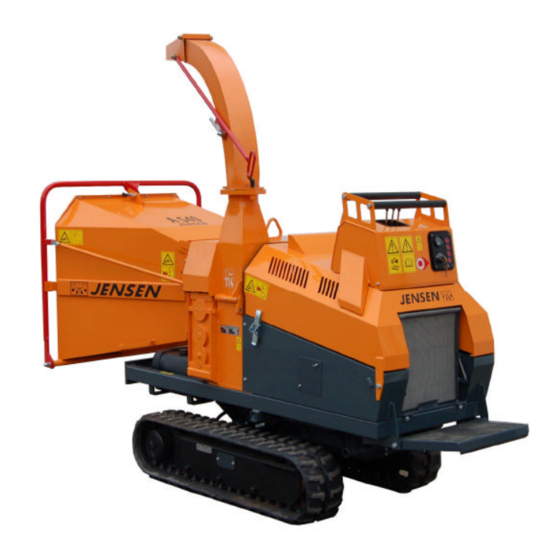
- Page 26 The Jensen Woodchipper is designed for reducing shrubs, bushes, branches, orchard and vineyard prunings etc., of unlimited length. The machine is for mounting an a tractor 3- point linkage and may also be supplied on a single or twin axle chassis for trailed use.
- Page 27 Suitable clothing Always wear - Safety helmet with face visor - Ear defenders - Thick gloves (Avoiding tight fitting gloves) - Overalls Avoid - Loose clothing - Ties - Anoraks with loose cords Starting the machine Always start with the feed rollers disengaged (‚stop‘ position). Feed brushwood into the machine with the thick end of the branch first.
- Page 28 Chipping length The chipping length is adjustable between 5mm – 20mm by turning the regulator of the hydraulic valve (larger chip size on special request). Cutting length can also be affected by the temperature of the hydraulic fluid so that it will be necessary to re-adjust during work.
- Page 29 Operating instructions Push the green button Disengage feeding: Push the green button a second time Engage feeding: Push the red button Stop Stop-lever Lever positions : Stop – Push lever towards machine Recommended instructions during operation Branch wood is to be fed always with heavier end towards retraction rollers. Should rotation of knives - disc drop during operation, push the disengaging lever, wait until disc reaches full operating rotation again, then activate feeding again.
- Page 30 Avoid from dirt when disassemble – mounting the counter-knife, clean the surfaces from dirt and chips. Attention: Use only spare parts origin JENSEN. No warranty in case of using other products. In case of spare part order always mention the number of this machine.
- Page 31 Noise level L (dB) Type of Load No-load machine running running A 141 Di A 141 Z A 231 Di A 231 Z A 328 Di A 328 Z A 328 ZUX A 425 Di A 425 Z A 540 Di A 530 Di A 530 Z...
- Page 32 Operating instructions infeed rollers STOP First touch on the STOP button is reverse, and the second touch is forward.
- Page 33 Greasing Instruction A540 Greasing instructions for 8-working-hours-shift Pos. Frequency of Designation Quantity Quantity of lubricant, lubrication free of Bearing of the knifedisc shaft maintenance free of spur gears of the rollers EP 220 ISO-VG-220 (1,5 Liter) maintenance Joint of the upper roller shaft weekly 2-3, Retinax A Bearing guidance of the bearing from...
- Page 34 Moving the machine Operating the undercarriage Straightforward translation. Push both levers forward to go straight- forward Pull both levers backward to go reverse. Right / left steering To steer right, push the left lever forward. To steer left, push the right lever forward.
- Page 35 Moving the machine Winch Attention! Please read and understand the separate winch operating manual before using the winch . The winch may not pull more than 2.700 kg. The winch has a lever which releases the rope clutch. Simply pull the lever and rotate it 90° . As soon as the rope is released it can be pulled out manually.
- Page 36 Moving the machine Maneuvering on soft ground Avoid driving on very soft grounds, which haven’t got enough resistance to bear the machine fast. Avoiding the maneuvering on inclined grounds Caution: maneuvering on inclined grounds is dangerous. Reduce the maneuvering speed in order to avoid inclinations or skiddings. As far as possiple avoid to turn on inclined grounds.
- Page 37 Moving the machine Operating the machine on sloping ground Caution: The recommended limit of operation on sloping ground should not exceed an incline of 20°. Above 20° the machine can to overbalance. Only for tracks with tilting mechanism! Using the tilting mechanism on sloping ground Caution: The recommended limit of operation for use of the tilting mechanism on sloping ground should not exceed an...
- Page 38 Moving the machine Transporting the machine Loading the machine on a low bed truck Always perform machine loading and unloading operation on a solid and level surface. IMPORTANT: Remember to use a ramp or a loading platform for loading and unloading the excavator.
- Page 39 Moving the machine Put wedges before and behind the tracks. Fasten each corner of the machine and fasten the front arm to the trailer with a chain or a suitable anchor. During the transport, position the fulel valve to OFF and make sure that the engine is in a flat position, in order to avoid fuel leaks.
- Page 40 Rubber track maintenance Checking track tension Stop your machine on flat and solid surface. Lift it in safe conditions and put stable supports under the undercarriage frame to properly support it. Measure distance A at the central roller of the undercarriage from the bottom of the roller to the rigid inside surface of the rubber track.
- Page 41 Rubber track maintenance DANGER It is not normal for the track to remain too tight after turning valve 1 counter-clockwise or for it to remain loose after introducting grease into grease nipple 2. Never try to remove the tracks or disassemble the track-stretching cylinder since pressure of the grease inside the track is extremely dangerous.
- Page 42 Rubber track maintenance C) Detachment of metal cores The metal core functions as an adhesive for the rubber, especially between the core itself and the steel cables. Detachment can be caused by excess track tension or by cable breakage for the following reasons: -metal cores have been rolled by a worn sprocket as indicated in the figure.
- Page 43 Rubber track maintenance Replacement of rubber tracks The grease contained in the hydraulic track is under pressure. Never loosen grease valve 1 for more than 1 turn. If the valve is loosened too much then pressurized grease may exit and cause DANGER severe injury to the machine operator.
- Page 44 Rubber track maintenance 3.Mesh the track links in the sprocket and place the other end of the track on the track- stretching wheel. 4.Rotate the driving gear in erverse (7) and pull the track soles inside the frame (8) 5.Position the track using a steel tube and turn the driving gear again.
- Page 45 Maintenance of drive geared motors Checking the oil level in the reduction unit Every 100 hours check the oil level in the reduction unit gearbox. Stop the hydraulic geared motor with plugs aligned horizontal. Remove the plugs as shown in fig. A and check that the oil level is up to their holes.
- Page 46 Operating Instructions for retraction roller gear General Read these instructions before you install, maintain or repair the gear boxes. Rotating shafts and hot parts could cause injury. All work has to be carried out by qualified personal only. Relevant safety regulations must be obeyed. Claims under guarantee can only be met if these instructions are complied with.
- Page 47 Operating Instructions for retraction roller gear Lubrication The gear boxes are not filled with oil. Mineral or synthetic oils may be used as lubricant. During the first operating hours an oil film at shaft seals and around the vent valve may appear.
- Page 48 KTR-N 40818 E KTR Kupplungstechnik ® C L A M P E X K T R 4 0 0 sheet: GmbH m o u n t i n g i n s t r u c t i o n s D-48407 Rheine edition: ®...
- Page 49 KTR-N 40818 E KTR Kupplungstechnik ® C L A M P E X K T R 4 0 0 sheet: GmbH m o u n t i n g i n s t r u c t i o n s D-48407 Rheine edition: The clamping set is generally delivered in assembled condition.
- Page 50 KTR-N 40818 E KTR Kupplungstechnik ® C L A M P E X K T R 4 0 0 sheet: GmbH m o u n t i n g i n s t r u c t i o n s D-48407 Rheine edition: Assembly...
- Page 51 KTR-N 40818 E KTR Kupplungstechnik ® C L A M P E X K T R 4 0 0 sheet: GmbH m o u n t i n g i n s t r u c t i o n s D-48407 Rheine edition: Disassembly...
- Page 52 Joint Clean PTO shaft. Operate quick- Connecting Actuate locking disconnect lock. Pull on the PTO drive or push depending shaft. on lock model. For excessive Wide-angle CV PTO Joint articulations, drive shaft articulation stop PTO shaft. Check joint articulation in operation and standstill 1.
- Page 53 Joint Dismantling Remove retaining ring. Place joint as shown above and use light hammer blows to drive up bearing bush. As a function of size, fix bearing bush into spezial tool SW23 or SW27 and remove bearing bush by light hammer blows onto the yoke or by rotating it.
- Page 55 Operating instructions HMCflex Service staff Version 2.0 Distribution and copying of this document, together with use and communication of its contents, are not permitted, except by express prior permission. Infringements are actionable for damages. All rights, including rights created by patent grant or registration of a utility model or design, are reserved. 1/23 ©...
-
Page 57: Brief Guide
HMCflex Operating instructions Brief guide HMCflex Overview • Operating / Fault LED Display Arrow keys SET key HMCflex, detailed front view Function of the keys Display of the chosen operating values; confirmation key for parameterisation Function key F2: Next display; increase value and number Function key F1: Previous display;... -
Page 59: Table Of Contents
Operating instructions HMCflex List of contents Brief guide ..........................2 HMCflex Overview ........................2 Function of the keys ......................2 General ........................4 Introduction ....................... 4 Target group ......................4 Important instructions for using the device ..............4 Repairing devices ..................... 5 Operating the HMCflex ..................... -
Page 61: General
HMCflex Operating instructions 1. General 1.1 Introduction The HMCflex offers a wide range of functions for the management and monitoring of both conven- tional and electronically controlled diesel engines. The settings can be individually configured for the widest variety of applications and different versions of the engine. For example, the HMCflex can pro- vide preheat, glow or afterglow for the engine up to 70 A, depending on the time and temperature. -
Page 62: Repairing Devices
Operating instructions HMCflex 1.4 Repairing devices If a repair should become necessary, send the device back to: ehb electronics GmbH Hans-Böckler-Str. 20 30851 Langenhagen Please ensure that a written description of the fault is included with the device. This will greatly assist the ehb electronics gmbh Service Department in identifying the fault, so the HMCflex can be more quickly repaired and returned. -
Page 63: Operating The Hmcflex
HMCflex Operating instructions 2 Operating the HMCflex 2.1 Connection The HMCflex is fixed to the floor using the clamps delivered with it or via the 3 x M6 screw fittings. The electrical connection of the HMCflex is achieved using a 19-pole German socket of the HDP 26-24-19 SE type. -
Page 64: Switching On / Off
Operating instructions HMCflex 2.2 Switching on / off The HMCflex is switched on via the ignition switch that is integrated into the control system (position 1) with terminal 30 activated. Once the preheating time is over, the engine can be started (position 2). In this way you get straight into the operating mode where the speed, operating hours, oil pressure and engine temperature are displayed. -
Page 65: Changing The Settings On The Hmcflex
HMCflex Operating instructions 3 Changing the settings on the HMCflex Where there is to be any change to the factory presettings, the HMCflex must be programmed after the initial installation. Programming is only possible with the engine at a standstill. You access the parameterisation mode by pressing the SET key and at the same time turning the ignition key to the ignition position. - Page 66 Operating instructions HMCflex Setup menu overview diagram *** Settings *** Pin no.: For the factory-set code for the setup menu, please enter 1000 with the arrow keys and confirm the individual figures with the SET key. Next you go into the "setup menu" field, as you can see from the diagram below.
- Page 67 HMCflex Operating instructions [6] autostart on/off SET on/off SET options RepEngStart SET 1-5 SET input duration SET 1-45s SET input pause SET 1-45s SET input exit SET Back to Options [7] emergency oil pressure SET shutd, alarm, without, CDown SET options temperature SET shutd, alarm, without, CDown SET options...
-
Page 68: Service Overview Diagram
Operating instructions HMCflex 3.1 Service overview diagram ***Service*** Pin no.: For the factory-set code for the service menu, please enter 1884 with the arrow keys and confirm the individual figures with the SET key. Next you go into the service menu field, as you can see from the diagram below. - Page 69 HMCflex Operating instructions [3] Security Options/ Input Settings Sub-menu Note Arrow key [1] Locking 1) languages SET options [2] sensors SET options [3] output SET options 4) glowtime SET options 5) altern. excitation SET SET options 6) autostart SET options 7) Emergency SET options 8) error delay...
-
Page 70: Daily Operating Hours Meter Overview Diagram
Operating instructions HMCflex 3.3 Daily operating hours meter overview diagram ***day hours*** Pin no.: For the factory-set code of the daily hour meter menu you enter 0000 please with the arrow keys and confirm the individual numbers with the set key. You arrive directly into the inquiry daily operation hours delete. -
Page 71: Chipper Overview Diagram
HMCflex Operating instructions 3.5 Chipper overview diagram For the factory-set code of the total hour meter menu you enter 6000 please with the arrow keys and confirm the individual numbers with the set key. [6] Chipper Options/ Input Settings Sub-menu Note Pfeiltaste Pulses / Rev... -
Page 72: Explanations Of The Adjustable Parameters
Operating instructions HMCflex Explanations of the adjustable parameters [1] Settings Parameters Explanations [1] language language You can choose between German, English, French and Spanish [2] sensors temperature The HMCflex can be factory set for the usual types of temperature sensor. The type of temperature monitoring is programmed under [10] Inputs/Outputs. - Page 73 HMCflex Operating instructions [4] glow times temp1 Temp 1 gives a value for the temperature-dependent preheating. Higher or lower value is automatically recognised by the management system by com- paring temp 1 and temp 2. The management system determines the glow times between the values in a linear way, depending on time temp 1 and time temp 2.
- Page 74 Operating instructions HMCflex cool down time (Cdown). disengage Monitoring of the start speed can be programmed as powering down (shutd), warning (alarm), without monitoring (without) or as power down with cool down time (Cdown). min.speed Monitoring of under speed can be programmed as powering down (shutd), warning (alarm), without monitoring (without) or as power down with cool down time (Cdown).
-
Page 75: Definition Of The Concepts Of Speed And Pulse Per Revolution
HMCflex Operating instructions [10] inputs/outputs All outputs are monitored for wire breaks, therefore the operating voltage is present on open outputs via a high-impedance resistor. The functions of the outputs can only be checked when they are under load. ext.Stop The external stop input can be programmed as NC, NO or without query. -
Page 76: Speed Measurement Through The Impulses Of Terminal "W
Operating instructions HMCflex 5.1 Speed measurement through the impulses of terminal "W" In order to be able to establish the frequency (alternator terminal "W"), two factors must be known. On the one hand, this involves the transmission ratio from the alternator to the crankshaft, which you can calculate as follows: Diameter belt pulley crankshaft Transmission ratio (i) =... -
Page 77: Inputs
HMCflex Operating instructions grammed temperature, the HMCflex retains the glowtime, which was programmed for the upper tem- perature. Chart of temperature-dependent preheating Chippercontrol In operation only the feed is controlled by the speed. The output return stroke can only be manually activated via external buttons. - Page 78 Operating instructions HMCflex Humidity 48 h As per SAE J1378 Vibration 6 h, 10-80 Hz 20 g As per SAE J1378 Shock 72 x, 9-13 ms 44 g 55 g As per SAE J1378 2 x 16 lines Alphanumeric Dimensions - housing 80 x 120 x 100 mm Fixing: On vibration dampers or clamps...
-
Page 79: Diagram
HMCflex Operating instructions 10 Diagram 22/23 © ehb errors and omissions excepted Operating instruction... -
Page 80: Document Information, History
Operating instructions HMCflex 11 Document information, history Project: HMCflex Type of document: Technical documentation Version: V2.0 Created on: Author: ehb electronics GmbH, Langenhagen Revisions: Version: Handling: Creation of provisional operating instructions 01.07.2008 H. Appen Additions and software adaptation, new wiring diagram 07.10.2008 Blume/Appen Additions and software adaptation, new wiring diagram... - Page 87 Service Schedule...
- Page 88 Regular maintenance plan every every every every every Internal combustion Internal combustion after first after first after first every after first 100 hours Wood chipper 8 hours 50 hours 200 hours 250 hours engine HATZ engine KUBOTA 5 hours 10 hours 20 hours 20 hours 50 hours...
- Page 89 Regular maintenance plan every every every every every every every every every every Internal combustion Internal combustion Wood chipper 1000 1500 2000 3000 engine HATZ engine KUBOTA hours hours hours hours hours hours hours months years years Change oil filter Change fuel filter Change fuel pre filter Maintenance...
- Page 90 Jensen Service GmbH Bahnhofstraße 20-22 D-24975 Maasbüll Tel.: 04634 / 9370-0 Telefax: 04634 / 1025 eMail: info@jensen-service.de http://www.jensen-service.de...
- Page 91 Original – Ersatzteile Original - spare parts Pièces de rechange d’origine...
- Page 92 Hydraulikanlage Hydraulic system Circuit hydraulique...
- Page 93 Hydraulikanlage Hydraulic system Circuit hydraulique Pos. Nr.: Bestell Nr.: Bezeichnung Designation Designation Anzahl Fig. Nr.: Order Nr.: pcs. Fig. Nr.: Ordre Nr.: pcs. Hydraulikschlauch tube tube 19155 Hydraulikschlauch tube tube 21117 Hydraulikschlauch tube tube 19181 Hydraulikschlauch tube tuyeau 21256 Hydraulikschlauch tube tuyeau 21253...
- Page 94 Motorantrieb Engine drive Propulsion moteur Pos. Nr.: Bestell Nr.: Bezeichnung Designation Designation Anzahl Fig. Nr.: Order Nr.: pcs. Fig. Nr.: Ordre Nr.: pcs. 16720 Keilscheiben Adapter pulley adapter adapteur pour poulie 3054 Schnorrsicherung washer rondelle 16191 Inbusschraube cylinder screw vis à téte cylindrique 14728 Keilscheibe pulley...
- Page 95 Hauptwelle Main shaft Arbre principal Pos. Nr.: Bestell Nr.: Bezeichnung Designation Designation Anzahl Fig. Nr.: Order Nr.: pcs. Fig. Nr.: Ordre Nr.: pcs. 65011 Hauptwelle main shaft arbre principal 2595 Paßfeder fitting key clavette plate chipper disc Messerscheibe volant à fenêtres -------- (see chipper (siehe Messerscheibe)
- Page 96 Messerscheibe Chipper disk Volant à fenêtres Pos. Nr.: Bestell Nr.: Bezeichnung Designation Designation Anzahl Fig. Nr.: Order Nr.: pcs. Fig. Nr.: Ordre Nr.: pcs. 65010 Messerscheibe knife disc disque a deux couteaux 2665 Messer knife couteau Z-Messer Z-knife Z-couteau 23149 Z-Messer Z-knife Z-couteau...
- Page 97 Gegenmesser Counter knife Contre couteau Pos. Nr.: Bestell Nr.: Bezeichnung Designation Designation Anzahl Fig. Nr.: Order Nr.: pcs. Fig. Nr.: Ordre Nr.: pcs. 9416 Gegenmesser counter knife contre couteau 9162 Spannpratze fixing device griffe d'arret 22022 Scheibe washer rondelle 5158 Sechskantschraube hexagon screw vis hexagonale 65009...
- Page 98 Walzeneinzug Retraction roller drive Transmission a rouleau Pos. Nr.: Bestell Nr.: Bezeichnung Designation Designation Anzahl Fig. Nr.: Order Nr.: pcs. Fig. Nr.: Ordre Nr.: pcs. 9496 Walzengetriebe roller transmission roleau transmission 955918 obere Einzugswalze upper roller rouleau superieure 956233 obere Z-Einzugswalze upper Z-roller Z-rouleau superieure 66009...
- Page 99 Auswerfer ejector Goulotte d' Ejection Pos. Nr.: Bestell Nr.: Bezeichnung Designation Designation Anzahl Fig. Nr.: Order Nr.: pcs. Fig. Nr.: Ordre Nr.: pcs. 66049 Auswerfer ejector Goulotte d' ejection 16535 Auswerferklappe adjustable trab Clapet articulé pour goulotte 16538 Verstellstange adjustment lever levier d' articulation 20021 Unterlegscheibe...
- Page 100 Einführtrichter, klappbar Infeed chute Tremie d'alimentation...
- Page 101 Einführtrichter, klappbar Infeed chute Tremie d'alimentation Pos. Nr.: Bestell Nr. Bezeichnung Designation Designation Anzahl Fig. Nr.: Order Nr.: pcs. Fig. Nr.: Ordre Nr.: pcs. 65030 Klapptrog komplett infeed chute cpl. tremie d´alimentation 65032 Schaltbügel infeed lever levier 9481 Lärmschutzvorhang rubber curtain rideau 9482 Schraubleiste...
- Page 102 Jensen Service GmbH Bahnhofstraße 20-22 D-24975 Maasbüll Tel.: 04634 / 9370-0 Telefax: 04634 / 1025 eMail: info@jensen-service.de http://www.jensen-service.de...
Need help?
Do you have a question about the A540 DiXL D-1703 Track and is the answer not in the manual?
Questions and answers