
Related Manuals for Jensen A141 XL ZX


Summary of Contents for Jensen A141 XL ZX
- Page 1 A141 Operating instructions and list of spare parts Type: A141 XL ZX Machine No.: 112105625 Construction year: 05/2021...
- Page 3 Translation of the original operating instructions Read the operating and safety instructions carefully before starting up the machine! These operating instructions belong to the machine. They must be handed over when selling or renting the machine. We always endeavor to improve our products; therefore we reserve the right to mount modifications and improvements that we consider to be appropriate.
- Page 5 The Jensen Company wishes a failure-free working for all operators. But for all that if there questions or troubles we effort to eliminate these as fast as possible.
- Page 7 (stamp / cachet) Datum Unterschrift (date) (signature) Vertrieb über: (distributed by / distribué par:) Jensen GmbH . Bahnhofstraße 20-22 . D-24975 Maasbüll Tel.: +49 46 34 93 70 0 . Fax: +49 46 34 10 25 E-mail: info@jensen-service.de . Homepage: www.jensen-service.de...
- Page 9 (stamp / cachet) Datum Unterschrift (date) (signature) Vertrieb über: (distributed by / distribué par:) Jensen GmbH . Bahnhofstraße 20-22 . D-24975 Maasbüll Tel.: +49 46 34 93 70 0 . Fax: +49 46 34 10 25 E-mail: info@jensen-service.de . Homepage: www.jensen-service.de...
- Page 11 (stamp / cachet) Datum Unterschrift (date) (signature) Vertrieb über: (distributed by / distribué par:) Jensen GmbH . Bahnhofstraße 20-22 . D-24975 Maasbüll Tel.: +49 46 34 93 70 0 . Fax: +49 46 34 10 25 E-mail: info@jensen-service.de . Homepage: www.jensen-service.de...
- Page 13 Konformitätserklärung Certificate of CE conformity Déclaration de conformité JENSEN GMBH Bahnhofstraße 20-22 D-24975 Maasbüll bestätigt hiermit, dass die von ihr hergestellte Maschine (Holzzerkleinerer) declares that the manufactured machine (wood chipper) déclare que la machine fabriquée (broyeur de branches) A141 Z...
- Page 15 IV. Technical data __________________________________________________________________________ General specifications A141 XL ZX machine type designated feeding hand-feeding max. wood diameter (mm) Noise impact Lwa idle (dB) load (dB) Main dimensions and weight length (mm) 2600 width (mm) 1700 height with ejector (mm) 2900...
- Page 17 Index Index Preamble Guarantee/Certificate of purchase III. Certificate of CE conformity Technical data Safety instructions ....................3 General safety instructions ................3 Setting up the machine .................. 4 Working with the woodchipper ............... 5 Self-propelled Woodchipper (combustion engine) ......... 6 PTO .......................
- Page 18 Index 5.3. Chip tray ...................... 30 5.4. Optional infeed controls and safety functions ..........31 5.5. Remote control (optional) ................32 5.6. Helmet safety switch off (optional) ............... 32 5.7. Motor machines (only for self-propelled machines) ........33 5.8. Chassis (optional) ..................42 5.9.
- Page 19 1. Safety instructions 1. Safety instructions General safety instructions It is only allowed to use the woodchipper for the designated feeding! The designated feeding can be found in the technical data of this manual. There can be conflicting information because of differences in machine types. The essential information in this case is the one that is favorable for the machine safety! The woodchipper is constructed according to present technical standards.
- Page 20 1. Safety instructions Setting up the machine The following points need to be followed when setting up the machine: 1. The woodchipper needs to be placed stable on a flat and firmly ground! 2. Stable stand of the machine with chassis frame with additional support legs: lower support legs and use wheel chocks.
- Page 21 1. Safety instructions Working with the woodchipper 1. Working with the machine is only allowed when all safety devices and covers are mounted. 2. It is not allowed to remove, to block or to disable the existing safety devices. 3. Additional to the instructions of this manual also the applying safety and accident prevention instructions need to be followed.
- Page 22 1. Safety instructions Self-propelled Woodchipper (combustion engine) 1. While starting up the engine use the starter only for a short period of time. Danger of overheating! Wait for the starter to cool down! 2. Attention while handling with fuel – enhanced fire danger! Never fuel up near open flames, sparks or hot machine parts.
- Page 23 1. Safety instructions Woodchipper as trailer/implement 1. The operator is responsible for the correct attachment and use of the machine especially when driving on public roads. 2. There is a risk of injury due to squeezing and shearing points when connecting the machine to the tractor or towing vehicle! 3.
- Page 24 1. Safety instructions 1.6.1 Additional weights 1. Watch for the right axle load of the front/rear axle when connecting the machine to the rear/front. Steerabality must be ensured. Adhere to the manufacturer's advice! 2. Watch out for load removal of front/rear axle of the tractor by using additional weights –...
- Page 25 1. Safety instructions Crane When the machine is designated for crane use only it is only allowed to feed it with a crane. When using a crane also observe the crane instruction manual. Attention! When feeding the machine the operator has to be outside of the pivoting range of the crane and the objects in the crane clamshell.
- Page 26 1. Safety instructions 1.9.1 Motor maintenance The maintenance of the motor has to be done according to the motor instruction manual. 1. Do not maintain while the motor is running! 2. When working on the motor, disconnect the battery (negative pole) and if existing pull of the spark plug connector! 3.
- Page 27 1. Safety instructions 7. Inverting of the connectors causes faulty operation due to contrary functions (forwards/backwards, lifting/lowering) – danger! 8. Check the hydraulic pipes for damage and deterioration regularly. Change if necessary at least every 5 years! The spare parts must correspond to the machine manufacture technical requirements! 1.9.4 Wheels and tires 1.
- Page 28 2. Meaning of the pictograms 2. Meaning of the pictograms Note The pictograms are placed near the source of danger. They should warn the operator of possible dangers. In the following passage explains the meaning of the pictograms. Always follow the meaning of the pictograms. Damaged or lost pictograms need to be replaced.
- Page 29 2. Meaning of the pictograms Pictogram Meaning Position order no.: 25243 Never reach into auger tube rotating auger. (drumchipper) VDMA-catalog no.: 15 order no.: 25244 Keep away from 1 per side right and rotating machine parts. left of the infeed VDMA-catalog chute no.: 17...
- Page 30 2. Meaning of the pictograms Pictogram Meaning Position order no.: 25248 Wait until all machine in-feed conveyer components have (optional) VDMA-catalog completely stopped no.: 25 before touching/stepping on them. Danger – flying order no.: 25249 infeed chute right objects; keep safe handed side distance from the VDMA-catalog...
- Page 31 2. Meaning of the pictograms Pictogram Meaning Position order no..: 25252 Use wheel chocks chassis front before machine is VDMA-catalog uncoupled or parked. no.: 52 order no.: Switch position infeed chute left 25253 Stop – Input – backwards order no.: Switch position infeed chute right 25254...
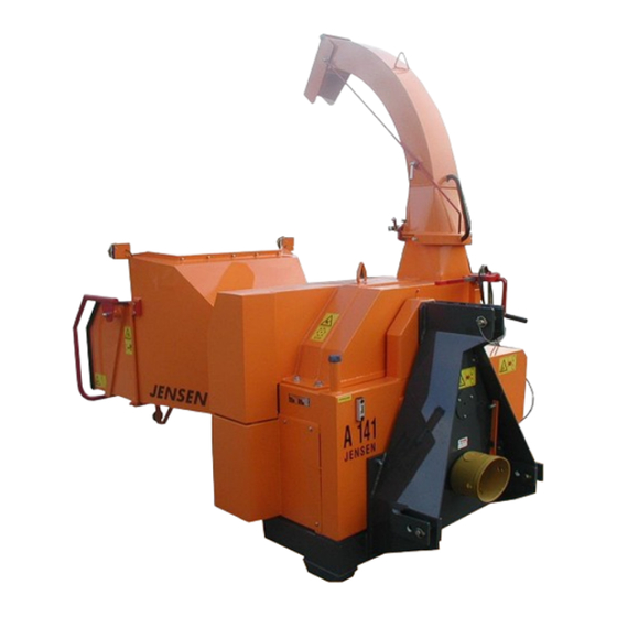
- Page 32 3. Designated use and function 3. Designated use and function Structure of the woodchipper Schematic display, differences in design and type possible. 1. control bar 2. cutting system 3. infeed 4. infeed chute 5. exhaust chute 6. ejector cap 7. impellent...
- Page 33 3. Designated use and function. Designated use 3.2.1 Operation purpose The Jensen woodchippers are designed as a movable machine for chipping brush and trunk wood of variable length. The max. trunk diameter can be found in the technical data. Examples for allowed materials: allowed: ...
- Page 34 3. Designated use and function Function of the woodchipper 3.3.1 Feeding The material gets fed into the infeed chute by hand or crane (according to the machine specifications). Danger! Always observe the safety advices when feeding the machine. There is a danger for life when persons get pulled in by brush wood or other objects.
- Page 35 3. Designated use and function. 3.3.4 Cutting system In the cutting system the infeeded material gets chopped. The cutting system is a compound of the rotating knife disk and the counter-knife. The material gets cut between those two parts of the machine. Paddles on the knife disk transport the cut material into the ejector.
- Page 36 4. Working with the woodchipper 4. Working with the woodchipper The steps that are described in this chapter can differ because of special machine specifications. Because of that it is possible, that some work steps for your machine differ from the steps that are described in this chapter. Personal protection Safety gloves Wear safety gloves while working with the machine.
- Page 37 4. Working with the woodchipper Mounting the machine onto a towing vehicle/tractor 4.1.1 Couple the trailer onto the towing vehicle (only for machines mounted on trailer) 1. Couple the trailer to the towing vehicle. Check the coupling for right fit and the latching of the safeguard.
- Page 38 4. Working with the woodchipper Setting up the woodchipper The following points must be followed when setting up the machine: 1. The woodchipper must be parked on a flat and stable ground. For machines with chassis: use support legs. For tractor mounted machines: ensure a safe stand of the tractor. 2.
- Page 39 4. Working with the woodchipper Positioning of the exhaust chute 1. Release the lock (1). 2. Rotate the exhaust chute in the desired position. 3. Fix the lock (1). 4. Release the lock for the exhaust cap (2). 5. Position the exhaust cap with the bar (3). 6.
- Page 40 4. Working with the woodchipper 4.4 The infeed chute Infeed flap Infeed flap Safety/control bar Safety/control bar Touch keys reverse intake stop stop Schematic display of the infeed chute, differences in design and type possible. 4.4.1 Safety bar and infeed control If the safety bar is located in the middle position the infeed is running forward (intake).
- Page 41 4. Working with the woodchipper manual safety interruption Schematic display, differences in design and type possible. 4.4.5 Setting up the infeed chute into work position 1. Depending on the model push the handle of the infeed flap or pull up the lock and turn it around 180°...
- Page 42 4. Working with the woodchipper Before starting up the machine Check the level of the hydraulic oil, refill if necessary. For motor machines: check the fuel level and the details of the manufacture (see motor manual). Check the lock of the ejector cap, safety covers, nuts and bolts for tight fit. Check the machine and safety covers for damage.
- Page 43 4. Working with the woodchipper 4.6.1.2 Turning off the motor 1. Put the throttle in lowest position. 2. Wait for the motor to achieve idle speed. 3. Turn the key counterclockwise into position 0 (off) and pull the key off. 4.6.1.3 Motor with disengageable clutch (optional) De-clutch the clutch only to start the motor, after starting the motor or for standstill or...
- Page 44 4. Working with the woodchipper Blockade of the machine In case of blockade turn off the machine immediately and secure it against accidental start up (pull off key of the machine/traction unit). Wait until the machine has come to a total stand still before opening or working on the machine. Remove the blockade with a suitable tool.
- Page 45 5. Operation and maintenance devices 5. Operation and maintenance devices 5.1. Hydraulic system Hydraulic components on the side of the infeed chute, schematic display, differences in design and type possible. 5.1.1. Chip size adjustment The chip size adjustment can be found on the side of the infeed chute. The speed of the infeed is adjustable with the turning knob (1) of the hydraulic valve manifold.
- Page 46 5. Operation and maintenance devices 5.2. Overload safety device In case that the knife disk speed is dropping under a defined speed the overload safety device stops the infeed. When the speed exceeds the switch-on-speed, the infeed is turned on again automatically. The stop and start speed can be set user-defined (see manual of the overload safety device).
- Page 47 5. Operation and maintenance devices 5.4. Optional infeed controls and safety functions 5.4.1. Touch keys (optional) The first touch reverses the infeed. Touching the key again puts the infeed to intake mode. STOP STOP Infeed controls for machines with touch keys. Schematic display, differences in design and type possible. 5.4.1.1.
- Page 48 5. Operation and maintenance devices 5.4.2. Palm switch (optional) 5.4.2.1. Palm switch with stop function (red) The red palm switches have an emergency stop function. Using the red palm switches stops the infeed. To turn on the infeed again the used palm switch needs to be reset by pulling it up and a Reset switch has to be pushed.
- Page 49 5. Operation and maintenance devices 5.7. Motor machines (only for self-propelled machines) 5.7.1. Motor control 5.7.1.1. Kubota motor control For machines that have a Kubota motor control all engine monitoring works from the Kubota control panel. coolant temperature gauge machine hour meter battery control light oil pressure control light ignition lock...
- Page 50 5. Operation and maintenance devices 5.7.1.3 machines with HCflex On machines where a engine monitoring system in the form of an HCflex is installed, the entire engine monitoring and control runs via the panel of the HCflex. The basic functions are described below. For further information, please refer to the enclosed operating instructions for the HCflex.
- Page 51 5. Operation and maintenance devices Set speed: After the engine has been started, the engine runs at idling speed (turtle symbol is visible). By pressing key 1 (12) the engine speed is increased (symbol hare is visible). Note: The motor does not switch to full throttle until the required working temperature has been reached and the warm-up time has elapsed.
- Page 52 5. Operation and maintenance devices Changing the operation display: The display can be changed by pressing the up or down arrow keys (8, 13). Display lower switch-off speed Display switch-on speed Display working speed Display upper switch-off speed Display set speed Display service interval...
- Page 53 5. Operation and maintenance devices Display engine oil pressure Display engine temperature Display system voltage Display engine power Display Addbluefill level Display soot load Display ash load...
- Page 54 5. Operation and maintenance devices Display of the hours since last regeneration Display Addblue quality Display exhaust gas temperature Selection (2) Suppress regeneration Display fuel level Display load pressure Suppress regeneration: If the working environment is not suitable for a high exhaust gas temperature (>600C°), the regeneration process should be suppressed.
- Page 55 5. Operation and maintenance devices 5.7.2. Pivotable motor bracket (optional) To pivot the motor bracket follow these points: 1. Make sure that the motor is switched off. 2. Take off the drive belt cover (1). 3. Remove the bolt (2) (AF 30) from the motor bracket support (between Service- Center and infeed chute) and open the eccentric lock (3).
- Page 56 5. Operation and maintenance devices 5.7.5. Service-Center (optional) Attention! Do not clean the Service-Center with a high pressure washer. Danger of damaging the electric system and water getting into the fuel tank. The Service-Center contains the following components: motor Control-Panel ...
- Page 57 5. Operation and maintenance devices 5.7.6. Slew ring lock (only for swiveling machines) To swivel the machine follow these points (only for manual slew ring): 1. Remove the lock (1). 2. Pull up the lever (2) and hold it up. 3.
- Page 58 5. Operation and maintenance devices 5.8. Chassis (optional) The max. permitted speed can be found on the rating plate. When uncoupling the machine, make sure that the support wheel/leg is lowered, the park brake (if existing) is putted on and wheel chocks are behind or rather in front of the wheels.
- Page 59 6. Maintenance 6. Maintenance 6.1. General maintenance information Also follow the maintenance information of our used co-manufactured parts (e.g. engine, clutch, crane etc.). Use only original or manufacture released spare parts. Basically the following maintenance work has to be done: 1.
- Page 60 6. Maintenance 6.2. Cleaning the machine Clean the machine with a pressure washer according to the material and amount (approx. once per month). For this: For motor machines: open the engine cover or rather swivel of the motor bracket. Open the ejector cap. Take of all safety covers.
- Page 61 6. Maintenance 6.3.1. Synoptical table: lubrication instructions for the 8-hours shift...
- Page 62 6. Maintenance 6.3.2. Position of the lubrication points type: A141/041, A233, A328/340 Schematic display, differences in design and type possible. 6.3.3. Position of the lubrication points type: A 425, A530, A540/550 Schematic display, differences in design and type possible.
- Page 63 6. Maintenance 6.4. Locking torque for bolted assemblies Attention! All bolted assemblies especially of the knife and of the chassis should be checked regularly, retighten if necessary. Unless otherwise noted the following locking torques apply. locking torque locking torque thread 8.8 (Nm) 10.9 (Nm) 14,5...
- Page 64 6. Maintenance 6.5.1. Open/close the ejector cap 1. Only open the ejector cap when the motor is turn off and the key is pulled off. 2. Make sure that the knife disk does not move (visual check through slots in the drive belt cover or at the PTO).
- Page 65 6. Maintenance 6.5.4. Diagram knife re-sharpening and wear limits A 141/041 A 231/240 knife wear limit knife wear limit 110 mm – 95 mm 80 mm – 60 mm A 328/340 A425/430 knife wear limit knife wear limit 100 mm – 70 mm 80 mm –...
- Page 66 6. Maintenance 6.5.5. Maintenance of the counter-knife The counter-knife has two cutting edges. When the cutting edge is blunt, the counter- knife can be dismounted. After cleaning the guideway the second cutting edge can be used. After the second cutting edge is blunt the counter-knife needs to be replaced.
- Page 67 6. Maintenance 6.5.7. Comb system (optional) The knives of the comb system (1) are hardened and cannot be re-sharpened. Worn out knives can be reused one time by turning them. Clear the surface when changing the knives. Comb-knives are located on the knife-disk and on the comb. Tighten up the bolts with a tightening torque of 49 Nm.
- Page 68 6. Maintenance 6.7. Hydraulic system 6.7.1. Run-in of the hydraulic system after changing the hydraulic oil Open the valve for the chip size adjustment (biggest chip size) – Vent the system by running the infeed unstressed 10 to 15 minutes in different valve positions (infeed speeds).
- Page 69 6. Maintenance 6.8. Electric system 6.8.1. Battery 1. Always disconnect the battery (negative pole) when working on the electrical system! 2. Observe the right order when disconnecting the battery – first negative then positive pole! – Connect the battery in invert order! 3.
- Page 70 6. Maintenance 6.9. Drive belts check weekly When machine is new or after drive belt change check the tension of the belts after 1-2 operation hours Correct tension if necessary Attention! Machine must be turned off! 6.9.1. Drive belt tension check 1.
- Page 71 6. Maintenance 6.9.3. Tensioning of the drive belts for self-propelled machines (combustion engine) (A425/430 pivotable): 1. Remove bolts of the drive belt cover. 2. Swing out the drive belt cover. 3. Loosen and remove the bolts of the engine bracket (according to machine type and design 3-4 bolts).
- Page 72 6. Maintenance 6.9.5. Tensioning of the drive belts with belt pulley For self-propelled machines (combustion engine) (A540/550 pivotable) 1. Swing out the drive belt cover. 2. Loosen bolts (1). 3. Pull down the belt pulley (3) with the clamping screw (2) until the tension is correct.
- Page 73 6. Maintenance 6.9.8. Drive belt change The procedure for changing belts is similar to tensioning the belts. 6.9.9. Guide pulleys The guide pulleys avoid flutter of the belt. The distance between the belt and the guide pulley should be 3-4 mm. 6.10.
- Page 74 6. Maintenance size tightening torque (Nm) filling position drain position filling hole bleeder hole oil level overflow hole drain hole 6.10.3 Lubricating oil Use oils type CL or CLP according to DIN 51517 (part 2 or 3). See our lubrication recommendation for free wheels below.
- Page 75 6. Maintenance 6.11. Feed rolls gear box Attention! Replacement gear boxes are provided without oil. Before putting into service the gearbox needs to be filled with oil! Check the oil level at the gauge-glass weekly. After the first 50 operating hours an oil change needs to be done. Mineral and synthetic oils can be used for the gear boxes.
- Page 76 6. Maintenance 6.12. Manual clamping set Clampex® KTR 400...
- Page 77 6. Maintenance...
- Page 78 6. Maintenance...
- Page 79 6. Maintenance...
- Page 80 6. Maintenance...
- Page 81 6. Maintenance...
- Page 82 6. Maintenance...
- Page 83 6. Maintenance...
- Page 84 6. Maintenance 6.13. Mounting and dismounting of the clamping set with Taper- Lock® Mounting the pulley 1. Clean and de-grease the bore and taper surfaces of the bush and the tapered bore of the pulley. Insert the bush in the pulley. Hub and line up the holes. Screw in bolt loosely.
- Page 85 6. Maintenance 6.14. Chassis Check tire pressure and wheel bolts regularly. Further information can be found in the chassis manual in the appendix. 6.15. Engine Maintenance has to follow the engine manufacturer specifications. Damage affected due to dust are not covered by the warranty! 6.16.
- Page 86 6. Maintenance 6.17.1. Troubleshooting overload safety device...
- Page 87 6. Maintenance 6.18. Tool kit All machine types Ring spanner, 19mm/24mm Fork spanner 19mm/24mm Fork spanner 13mm/17mm Allen key 8 mm, 10 mm Counter knife drift punch Knife spacer 0,5 mm according to number of knives blocking tool for the knife disc Type A530 Additional 24 mm socket ½...
- Page 88 6. Maintenance 6.19. Spare parts Use only original Jensen spare parts. The order number for the original spare parts can be found in the list of spare parts. You can order spare parts over the Jensen sales and distribution and at authorized service centers.
- Page 89 6. Maintenance 6.20. Maintenance schedule...
- Page 90 7. Storage and disposal of the machine 7. Storage and disposal of the machine 7.1. Storage 7.1.1. Store the machine For storage of the machine longer than 3 month: 1. Clean up the machine properly (see cleaning the machine) 2. Lubricate the machine (see lubrication instructions) 3.
- Page 91 Maschinenspezifisches folgenden Seiten befinden sich Betriebsanleitungen Maschinenhersteller verbauten Zulieferteilen maschinenspezifischer Komponenten wie z.B. Fernbedienung, Kran, Motor, etc und deren Handhabung. Machine-specific information Please find on the following pages the manuals of our sub-suppliers and components we use for special machineries: remote control, crane, engine, etc and how to use them.
- Page 93 Operating Instructions HC 960 Version 2.1 The dissemination of information from, and reproduction of, these documents as well as the utilisation and communication of their content is not permitted unless specifically authorised. Any infringement shall result in liability for damages. All rights are reserved, particularly with regard to the granting of patents or registration of utility models.
-
Page 94: Table Of Contents
HC960 Operating Instructions Table of contents General information ....................2 1.1. Operating states ...................... 2 1.2. HC960 operating modes ..................2 Meaning of parameters ....................2 Graphical representation of functions ................4 Programming the parameters ..................5 Chipper control sequence (Normal RPM = 0) .............. 6 Chipper control sequence (Normal RPM >... -
Page 95: General Information
HC960 Operating Instructions 1. General information The HC960 chipper controller includes automatic control for the feed rollers of a wood chipper, a revolu- tion counter, a daily counter and a total operating hours counter. When operating the HC960, a distinction is made between two different operating states. - Page 96 HC960 Operating Instructions Underspeed Deviation from the target speed. If the speed falls below this minimum speed, the feeder is stopped to allow the blade shaft to reach its target speed again. The minimum speed can be entered both as an absolute value and as a percentage deviation from the target speed.
-
Page 97: Graphical Representation Of Functions
HC960 Operating Instructions 3. Graphical representation of functions This representation refers to the software S02422. * The output corresponds to the respective pictogram on the pin assignment (page 9). 4/14 Version 2.1 © Errors excepted Bedienungsanleitung.doc • Stand/Version: 25.02.2005/00 • Layout: Gottschalk • \\Ehelec-nts-000\EHELEC\Iso 9001\Formblätter\Vorlagen... -
Page 98: Programming The Parameters
HC960 Operating Instructions 4. Programming the parameters The parameters must always be programmed when the machine is at standstill. To access the parameter setting in operating mode, switch on the device while holding down the set button. Press the set button until the display shows "*** parameter ***". -
Page 99: Chipper Control Sequence (Normal Rpm = 0)
HC960 Operating Instructions 5. Chipper control sequence (Normal RPM = 0) 6/14 Version 2.1 © Errors excepted Bedienungsanleitung.doc • Stand/Version: 25.02.2005/00 • Layout: Gottschalk • \\Ehelec-nts-000\EHELEC\Iso 9001\Formblätter\Vorlagen... -
Page 100: Chipper Control Sequence (Normal Rpm > 0)
HC960 Operating Instructions 6. Chipper control sequence (Normal RPM > 0) 7/14 Version 2.1 © ehb Errors excepted Y:\Vertrieb\01 Produkte\01 Produktinformationen Vertrieb\HC 960\Betriebsanleitung\HC 960_BA_V2.1_EN_23.11.2020_.docx Bedienungsanleitung.doc • Stand/Version: 25.02.2005/00 • Layout: Gottschalk • \\Ehelec-nts-000\EHELEC\Iso 9001\Formblätter\Vorlagen... -
Page 101: Operating Hours Counter
HC960 Operating Instructions 7. Operating hours counter The HC960 has two independent operating hours counters: A resettable daily operating hours counter, which can be used for maintenance intervals, for example, and a settable total operating hours counter. While the blade shaft rotates, its speed is automatically displayed. If you wish to display the daily operat- ing hours instead, briefly press the set button once in fully automatic mode (Normal RPM greater than zero). -
Page 102: Amphenol Connector
HC960 Operating Instructions 9. Amphenol connector 9/14 Version 2.1 © ehb Errors excepted Y:\Vertrieb\01 Produkte\01 Produktinformationen Vertrieb\HC 960\Betriebsanleitung\HC 960_BA_V2.1_EN_23.11.2020_.docx Bedienungsanleitung.doc • Stand/Version: 25.02.2005/00 • Layout: Gottschalk • \\Ehelec-nts-000\EHELEC\Iso 9001\Formblätter\Vorlagen... -
Page 103: Amp Connector
HC960 Operating Instructions 10. AMP connector 10/14 Version 2.1 © Errors excepted Bedienungsanleitung.doc • Stand/Version: 25.02.2005/00 • Layout: Gottschalk • \\Ehelec-nts-000\EHELEC\Iso 9001\Formblätter\Vorlagen... -
Page 104: Technical Data
HC960 Operating Instructions 11. Technical data Electrical data: Voltage range 8-32V Operating temperature -20°C to +70°C temporary discoloration of the display Storage temperature -30°C to +80°C Inputs Speed input for inductive encoder Outputs Output for hydraulic valve 2A) semiconductor, short-circuit protected Total operating hours counter 0…99999 h Daily operating hours counter... -
Page 105: Important Information On Use
HC960 Operating Instructions 12. Important information on use Test Before delivering the installed HC960 to the end user, a brief functional test should be carried out in the peripheral equipment that is to be used. This device is to be operated only in combination with the supplied accessories. Protect the device from moisture and dust. -
Page 106: Repairing Devices
HC960 Operating Instructions 13. Repairing devices Should the device require repair work, please return it to: ehb electronics gmbh Hans-Böckler-Str. 20 30851 Langenhagen GERMANY Please make sure that you include a written fault description. This will facilitate the work of the ehb electronics gmbh service department and ensure faster return of your HC 960. -
Page 107: Documentation Information And History
HC 960 Translation of the original operat- ing manual 15. Documentation information and history HC 960 Project: Type of document: Technical document Version: 27/02/2007 Prepared on: Mühlhausen Prepared by: ehb electronics gmbh, Hanover 16. Revisions: Version: Preparation/Revisions: Prep./Rev. Preparer/Re- date: viser(s): Consolidation DE, EN, IT 23/06/2006... - Page 109 Not-Halt mit Reset Knopf (Sensorstop) 06 2021 Klemmleiste Emergency stop with reset button (Sensor stop) 1=Spa nnung sversorgu ng Klemme 15 (+12-24V) Arrêt d'urgence avec Bouton de réinitialisation (Arrêt du capteur) 2=Spa nnung sversorgu ng Masse (0V) blau / blue / bleu 3=Magne tventilstecker IFM +12-24V (Klemme1) blau / blue / bleu...
- Page 111 Elektronik-Schaltplan connection diagram schéma des connexions Pos. Nr.: Bestell Nr.: Anzahl Fig. Nr.: Order Nr.: Bezeichnung Designation Designation pcs. Fig. Nr.: Ordre Nr.: Pcs. 40510 Sensortaster grün green sensor capteur vert 968372 Sensortaster rot red sensor capteur rouge 40511 Kabel Sensortaster sensor cable le câble capteur 966945...
- Page 113 Original – Ersatzteile Original - spare parts Pièces de rechange d’origine...
- Page 114 Hydraulikanlage hydraulic system circuit hydraulique...
- Page 115 Hydraulikanlage hydraulic system circuit hydraulique Pos. Nr.: Bestell Nr.: Anzahl Fig. Nr.: Order Nr.: Bezeichnung Designation Designation pcs. Fig. Nr.: Ordre Nr.: Pcs. 961607 Saugfilter suction filter filtre 965181 Filterpatrone cartridge for filter cartouche pour filtre 9557 Hydraulikpumpe pump pompe 19442 Druckfilter pressure filter...
- Page 116 Pumpenantrieb hydraulic pump drive Propulsion pour pompe hydraulique...
- Page 117 Pumpenantrieb hydraulic pump drive Propulsion pour pompe hydraulique Pos. Nr.: Bestell Nr.: Anzahl Fig. Nr.: Order Nr.: Bezeichnung Designation Designation pcs. Fig. Nr.: Ordre Nr.: Pcs. 2345 Pumpenhalter mounting plate flange a pompe 10067 Keilscheibe pulley poulie 40466 Kraftband power belt courroie 2346 Federring...
- Page 118 Hauptwelle Main Shaft Arbre Principal...
- Page 119 Hauptwelle Main Shaft Arbre Principal Pos. Nr.: Bestell Nr.: Bezeichnung Designation Designation Anzahl Fig. Nr.: Order Nr.: pcs. Fig. Nr.: Ordre Nr.: pcs. Sechskantschraube hexagon head screw boulon 2174 Impulsgeber pulser donneur d´impulsions 40456 Flanschzapfen pivot flange bride de maneton 16474 Spannsatz clamping set...
- Page 120 2-Messer-Fensterscheibe chipper disc volant à fenêtres Bauartbedingte Bildabweichung möglich! Deviations from figures possible! Differences symboliques possibles!
- Page 121 2-Messer-Fensterscheibe chipper disc volant à fenêtres Pos. Nr.: Bestell Nr. Bezeichnung Designation Designation Anzahl Fig. Nr.: Order Nr.: pcs. Fig. Nr.: Ordre Nr.: pcs. 957673 2-Messer-Fensterscheibe window disc volant à fenêtres 1999 Schraube screw boulon 1998 Mutter ecrou Messerschraubenmutter ecrou Federring spring ring rondelle elastique...
- Page 122 Walzenantrieb roller drive transmission à rouleau...
- Page 123 Walzenantrieb roller drive transmission à rouleau Pos. Nr.: Bestell Nr.: Anzahl Fig. Nr.: Order Nr.: Bezeichnung Designation Designation pcs. Fig. Nr.: Ordre Nr.: Pcs. 130090 Druckbalken kpl. pressure bar cpl. bouterolle de pression cpl. 958050 Welle shaft arbre 10582 Zugfeder tension spring ressort 16251...
- Page 124 Einführtrichter, klappbar infeed chute tremie d'alimentation...
- Page 125 Einführtrichter, klappbar infeed chute tremie d'alimentation Pos. Nr.: Bestell Nr.: Anzahl Fig. Nr.: Order Nr.: Bezeichnung Designation Designation pcs. Fig. Nr.: Ordre Nr.: Pcs. 972748 Schaltbügeladapter pivot point for infeed lever pivot de levier 965435 Spannelement clamping element elément de serrage 40510 Sensortaster grün green sensor...
- Page 126 Not-Stopp Elektrokomponenten danger-stop electrical components arrêt d'urgence composants électriques...
- Page 127 Not-Stopp Elektrokomponenten danger-stop electrical components arrêt d'urgence composants électriques Pos. Nr.: Bestell Nr.: Anzahl Bezeichnung Designation Designation Fig. Nr.: Order Nr.: pcs. Fig. Nr.: Ordre Nr.: Pcs. 40186 Not - Aus Buzzer emergency stop buzzer buzzer d'arrêt d'urgence 967566 Reset Knopf reset button bouton de réinitialisation 80166...
- Page 128 Auswerfer ejector goulotte d'ejection...
- Page 129 Auswerfer ejector goulotte d'ejection Pos. Nr.: Bestell Nr.: Anzahl Fig. Nr.: Order Nr.: Bezeichnung Designation Designation2 pcs. Fig. Nr.: Ordre Nr.: Pcs. 965365 Auswerferstutzen ejector lower part manchon 965366 Auswerferbogen ejector Goulotte d` Ejection 972685 Auswerferklappe adjustable trap clapet articulé 17635 Verstellstange adjustment lever...
- Page 130 Zentralschmierung central lubrication graissage central...
- Page 131 Zentralschmierung central lubrication graissage central Pos. Nr.: Bestell Nr.: Größe Fig. Nr.: Order Nr.: Bezeichnung Designation Designation size. Fig. Nr.: Ordre Nr.: taille. 966239 Schmiernippelblock lubrication nipple graisseur 71883 Schmiernippelblock lubrication nipple graisseur 71106 Schmiernippelblock lubrication nipple graisseur 961934 Schmiernippelblock lubrication nipple graisseur 961933...
- Page 132 Jensen GmbH Bahnhofstraße 20-22 D-24975 Maasbüll Tel.: 04634 / 9370-0 Telefax: 04634 / 1025 eMail: info@jensen-service.de http://www.jensen-service.de...
Need help?
Do you have a question about the A141 XL ZX and is the answer not in the manual?
Questions and answers