Table of Contents
Advertisement
Quick Links
INSTALLATION & MAINTENANCE MANUAL
Installation and service must be performed by a qualified service installer, service agency or the gas supplier.
IMPORTANT:
THIS
MANUAL
MAINTENANCE OF THIS EQUIPMENT. READ AND FOLLOW THE INFORMATION IN THIS MANUAL AND ALL OTHER
PROVIDED INSTRUCTIONS, LABELS AND MARKINGS BEFORE INSTALLING, OPERATING OR SERVICING THIS UNIT.
TO THE INSTALLER: After installation, these instructions must be given to the equipment user or left near the appliance.
SPECIAL INSTRUCTIONS TO THE OWNER: Retain this manual for future reference. These instructions contain
important information that will help you in maintaining and operating this appliance.
CONQUEST
MODELS (50, 60, 70, 80) L 130 A-GCML
MODEL (40) L 130 A-GCL
CONTAINS
INFORMATION
PVI INDUSTRIES, LLC - Fort Worth, Texas 76111 - Web
®
WATER HEATER
REQUIRED
FOR
INSTALLATION,
OPERATION
www.pvi.com
- Phone 1-800-433-5654
PV500-60 04/16
AND
Advertisement
Table of Contents

Related Manuals for PVI Industries 50 L 130 A-GCML


Summary of Contents for PVI Industries 50 L 130 A-GCML
- Page 1 SPECIAL INSTRUCTIONS TO THE OWNER: Retain this manual for future reference. These instructions contain important information that will help you in maintaining and operating this appliance. PVI INDUSTRIES, LLC - Fort Worth, Texas 76111 - Web www.pvi.com - Phone 1-800-433-5654...
-
Page 2: Table Of Contents
® CONQUEST WATER HEATER TABLE OF CONTENTS Safety Considerations Product Description Water Heater Installation Checking Equipment Before You Install Codes Electrical Requirements Handling and Locating the Water Heater Clearances to Combustible Surfaces Service Clearances General Piping Guidelines Inlet and Outlet Connections Building Return Piping Condensate Drain, Trap &... - Page 3 ® CONQUEST WATER HEATER Operating and Safety Controls Temperature and Pressure Relief Valve(s) Cathodic Protection Electronic Low Water Cut-off Operating Temperature Control High Water Temperature Limit Control TEMPTRAC Electronic Controller Panel 10.1 Principal of Operation 10.2 Upper LED Readout 10.3 Lower LED Readout 10.4 Control Buttons 10.5 To View the Setpoint 10.6 To Change the Setpoint...
-
Page 4: Safety Considerations
® CONQUEST WATER HEATER SAFETY CONSIDERATIONS WARNING: If the information in the supplied manual(s) is not followed exactly, a fire, explosion or exposure to hazardous materials may result, causing property damage, personal injury or death. FOR YOUR SAFETY • Do not store or use gasoline or other flammable vapors or liquids in the vicinity of this or any other appliance. WHAT TO DO IF YOU SMELL GAS •... - Page 5 ® CONQUEST WATER HEATER IMPORTANT SAFETY NOTE It takes only 5 seconds of skin contact with 140°F water to cause a second degree burn! You must protect against high water temperatures at all lavatories, tubs, showers and other points of hot water contact. Accidental scalding from high water temperatures is a greater risk in some types of installations.
-
Page 6: Product Description
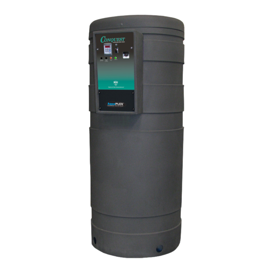
® CONQUEST WATER HEATER PRODUCT DESCRIPTION Component, Controls and Connection Locations (Locations May Vary) PV500-60 04/16... -
Page 7: Water Heater Installation
® CONQUEST WATER HEATER WATER HEATER INSTALLATION 3.1 Checking Equipment Before You Install • Inspect the unit completely upon receipt from the freight carrier before signing the bill of lading. Inspect the appliance and all accompanying parts for signs of impact or mishandling. Verify the total number of pieces shown on packing slips with those actually received. -
Page 8: Clearances To Combustible Surfaces
® CONQUEST WATER HEATER 8. Use the following diagram to locate anchors or attachment points, when connecting the heater to the floor. Typical concrete anchors: 5/16" x 1-3/4" double expansion shield. 3.5 Clearances To Combustible Surfaces The minimum clearance to combustible material is 15" from the top, 24" from the front and zero clearance (0") from the sides and back of the water heater. -
Page 9: General Piping Guidelines
® CONQUEST WATER HEATER GENERAL PIPING GUIDELINES 4.1 Inlet and Outlet Connections 1. Use only non-ferrous water piping and fittings. Do not use galvanized pipe or fittings. Use of ferrous or galvanized pipe or fittings can cause rust to form. 2. - Page 10 ® CONQUEST WATER HEATER SINGLE STORAGE WATER HEATER WITH SUPPLEMENTAL STORAGE TANK TWO WATER HEATERS WITH REVERSE RETURN PIPING PV500-60 04/16...
-
Page 11: Condensate Drain, Trap & Disposal
® CONQUEST WATER HEATER CONDENSATE DRAIN, TRAP & DISPOSAL The Conquest water heater produces a significant amount of condensate. The condensate drain is under slightly positive flue pressure, so the provided 3/4" PVC condensate trap must always be used. This trap is sized and designed to fill with the proper amount of condensate to create a liquid barrier to prevent flue gases escaping through the condensate drain into the installed space. -
Page 12: Condensate Neutralization System (Optional)
® CONQUEST WATER HEATER 5.1 Condensate Neutralization System (optional) Condensate is only slightly acidic (3-5 PH), however this slight acidity can be neutralized by routing it through an optional PVI Condensate Neutralization System. Some “authorities having jurisdiction” require such neutralization before condensate disposal through a suitable drain. -
Page 13: Gas Supply And Piping
® CONQUEST WATER HEATER Condensate Trap With Optional Condensate Neutralizer Located Below Conquest GAS SUPPLY AND PIPING Verify the type of gas specified on rating plate is supplied to the unit. This unit is orificed for operation up to 2000 feet altitude. -
Page 14: Manifold Pressure
® CONQUEST WATER HEATER 6.4 Manifold Pressure Measure at the pressure tap located downstream side of the manual valve closest to the burner. The rated manifold pressure appears on the product data label located near the front of the appliance. 6.5 Gas Piping Size Do not use the gas pipe connection size to determine the gas supply piping. -
Page 15: Appliance Isolation During Gas Supply Piping Pressure Test
® CONQUEST WATER HEATER 6.6 Appliance Isolation During Gas Supply Piping Pressure Test 1. The appliance and its provided manual shutoff valve must be disconnected from the gas supply piping system during any pressure testing of that system at test pressures in excess of ½ PSI (3.5 kPa). 2. -
Page 16: Maximum Allowed Remote Combustion Air Inlet Length
® CONQUEST WATER HEATER • All Air From Inside The Building: Follow the requirements of NFPA 54 National Fuel Gas Code, ANSI Z223.1 section “Indoor Combustion Air.” • Combination Of Air From The Indoors And From The Outdoors: Follow the requirements of NFPA National Fuel Gas Code, ANSI Z223.1 section “Combination Indoor and Outdoor Combustion Air.”... -
Page 17: Remote Combustion Air Cap
® CONQUEST WATER HEATER The following remote air duct information is provided for use in design calculations, if needed. Remote Air Duct Specifications Input MBtu/h Required Air (SCFM) 7.3 Remote Combustion Air Cap A suitable remote air termination must be used to prevent water, debris, animals or obstructing material from entering the remote air supply. -
Page 18: Optional Filter Box For Dusty Or Dirty Combustion Air
® CONQUEST WATER HEATER 7.6 Optional Filter Box for Dusty or Dirty Combustion Air The field installed optional air inlet filter box must be attached to the combustion air inlet on any appliance located where it is exposed to dusty, dirty or lint filled combustion air. Replace the filter on a 3 to 6 month schedule, or more often, based on severity of contamination Inadequate combustion air or non-combustible particulate matter such as dust, dirt, dryer lint, concrete dust, dry wall dust or the like can be drawn in with combustion air and block burner ports. -
Page 19: Venting
® CONQUEST WATER HEATER VENTING 8.1 Venting the CONQUEST: All Conquest models use the positive pressure generated by the burner system blower to push combustion products out of the vent. Since the vent system is under positive pressure and must be capable of containing condensate, it must be constructed of schedule 40 or 80 solid PVC or CPVC pipe. -
Page 20: Maximum Vent Length
® CONQUEST WATER HEATER Testing for leaks – Once the vent system is installed, it must be checked to confirm all joints in the vent system are air and water tight. After the vent is assembled, close the end of the vent with a taped plastic bag or some other temporary closure. -
Page 21: Vertical Or Horizontal Vent Termination
® CONQUEST WATER HEATER The following vent information is provided for use in design calculations, if needed. Venting Specifications Max Vent Combustion Air Input MBtu/h Volume (cfm) Press. " W.C. 8.3 Vertical or Horizontal Vent Termination: 1. The vent terminal must have a minimum clearance of 4 feet (1.22 m) horizontally from, and in no case be located above or below, unless a 4 foot (1.22 m) horizontal distance is maintained from electric meters, gas meters, regulators and relief equipment. -
Page 22: Concentric Vent For Combustion Air And Exhausting Flue Products
® CONQUEST WATER HEATER Conventional Venting Through the Wall Venting Combining Vents with a Draft Inducer 8.5 Concentric Vent for Combustion Air and Exhausting Flue Products Concentric venting, to enable a single side wall or roof penetration for both combustion air and flue exhaust terminations, is available for the Conquest following the instructions located at www.pvi.com/vent-design.html. -
Page 23: Cathodic Protection
® CONQUEST WATER HEATER 9.2 Cathodic Protection PVI water heaters do not utilize cathodic protection. However, in hot water systems utilizing cathodic protection, hydrogen gas can be produced when the hot water system has not been used for a long period of time (generally two weeks or more). -
Page 24: Temptrac Electronic Controller Panel
® CONQUEST WATER HEATER TEMPTRAC™ ELECTRONIC CONTROLLER PANEL 10.1 Principle Of Operation The water heater operates to satisfy the setpoint of the TempTrac digital control whose sensor is located near the top of the water heater tank. Demand (flow) will typically create a drop in temperature, thus activating the water heater to add heat to the stored water. -
Page 25: To View The Setpoint
® CONQUEST WATER HEATER 10.5 To View the Setpoint • Push and release the SET key to see the set point value. • To return to normal display, press SET + UP or wait 15 seconds without pressing any key. 10.6 To Change The Setpoint •... -
Page 26: Led Display Alarm Messages
® CONQUEST WATER HEATER 10.8 LED Display Alarm Messages Alarm messages are displayed in the upper LED readout and alternate with the default display. An alarm LED ICON is also illuminated. ALARM RECOMMENDED CAUSE RESULTS OF ALARM CONDITION MESSAGE ACTION Inlet temperature sensor is not connected or is Check wiring and sensor “P1”... -
Page 27: Remote Connections - Terminal Strip
® CONQUEST WATER HEATER REMOTE CONNECTIONS – TERMINAL STRIP 11.1 Making BMS/BAS remote connections for analog and binary (on/off) signals A terminal strip for the remote connection is located behind the bottom control panel door and is accessed removing the four thumb screws a lifting the hinged door. IMPORTANT: Do not use single strand bell wire for remote field connections to terminals R1-R2 and C1-C2. -
Page 28: Sequence Of Operation
® CONQUEST WATER HEATER SEQUENCE OF OPERATION 1. Incoming 120VAC a. Full time power to the Fuse b. Full time power to the Main Control Switch 2. Power On - When the main control switch is turned on: a. 120V is applied to the step-down transformer (24V) b. -
Page 29: Initial Startup
® CONQUEST WATER HEATER 9. Loss of Flame Signal a. If the igniter fails to sense flame at any time, the igniter and gas valve will be de-energized and the flame control will reset and begin the call-for-heat sequence again. This will occur 3 times (one time if CSD-1) before the flame control will lockout. - Page 30 ® CONQUEST WATER HEATER 2. Fill system tank with water. a. Close the drain valve. b. Open a nearby hot water faucet to permit the air in the system to escape. c. Fully open the cold water inlet valve to fill the tank. d.
- Page 31 ® CONQUEST WATER HEATER 15. Turn-on main gas shutoff valve. 16. If the TempTrac operating control switch is closed (indicated by the icon), the burner blower should come on and pre-purge begins. 17. If nothing happens, check for a safety device lockout. Some safety devices such as the Low Water Cut-off, Gas Pressure Switches and the High Temperature limit will require manual reset after lockout and therefore can be easily identified.
- Page 32 ® CONQUEST WATER HEATER Gas Train Illustration for Model 40 (Optional components may not be shown) Gas Train Illustration for Models 50 through 80 (Optional components may not be shown) PV500-60 04/16...
- Page 33 ® CONQUEST WATER HEATER Alternate Gas Train Illustration for Models 50 through 80 (Optional components may not be shown) PV500-60 04/16...
-
Page 34: Nsf Food Service Installation Guidelines
® CONQUEST WATER HEATER NSF FOOD SERVICE INSTALLATION GUIDELINES All Conquest water heater models that have the Intertek ETL Sanitation mark on the information decal affixed to the front of the appliance are listed to NSF 5-2009e. This section provides additional information for architects, designers, and contractors in food service installations requiring compliance with NSF codes. -
Page 35: Troubleshooting Guide
® CONQUEST WATER HEATER TROUBLESHOOTING GUIDE Problem Probable Cause Corrective Action Power Supply Check fuse and/or circuit breaker. Check if On-Off switch is illuminated when on. If not check On-Off Switch panel fuse or incoming power. Check that the operating temperature control is set higher Temperature Control than the temperature of the water heater. -
Page 36: Replacement Parts
® CONQUEST WATER HEATER REPLACEMENT PARTS REPLACEMENT PARTS PV500-60 04/16... -
Page 37: Burner Assemblies
® CONQUEST WATER HEATER 16.1 Burner Assemblies Burner Assembly Illustration for Model 40 (Optional components may not be shown) PV500-60 04/16... - Page 38 ® CONQUEST WATER HEATER Burner Assembly Illustration for Models 50 through 80 (Optional components may not be shown) PV500-60 04/16...
-
Page 39: Control Panel Enclosure Component Layout And Replacement Pn's
® CONQUEST WATER HEATER 16.2 Control Panel Enclosure Component Layout and Replacement PN’s LIST OF MATERIALS ITEM PART NO. DESCRIPTION CONTROL PANEL COMPONENTS TempTrac Control 122644 TempTrac Kit for 399 MBtu/H 122645 TempTrac Kit for 500 MBtu/H 122646 TempTrac Kit for 600 MBtu/H 122647 TempTrac Kit for 700 / 800 MBtu/H 70573... -
Page 40: Component Wiring And Conduit Routing Details
® CONQUEST WATER HEATER 16.3 Component Wiring and Conduit Routing Details PV500-60 04/16... -
Page 41: Periodic Maintenance
Do not remove filter until a suitable replacement is available. The air filter is available through your PVI Industries Dealer or use any standard capacity MERV 7, pleated air filter, 12"x24"x1". - Page 42 13. All replacement parts are available through your PVI Industries Dealer. If you need assistance identifying or contacting your local dealer, you may contact PVI Industries, LLC directly at the address and telephone number located on the first and last page of this manual.
-
Page 43: Recommended Maintenance Schedule
® CONQUEST WATER HEATER RECOMMENDED MAINTENANCE SCHEDULE Annual Maintenance a. Check all joints and pipe connections for tightness, corrosion or deterioration. b. Check the electronic-ignition system for quick ignition and a proper flame signal. c. Check all safety controls including thermostats for proper operation. d. - Page 44 MODEL NUMBER: SERIAL NUMBER: INSTALLATION DATE: ® , LLC • 3209 Galvez Ave. • Fort Worth, Texas 76111 • Phone 1-800-433-5654 • PVI INDUSTRIES www.pvi.com PV500-60 04/16...
Need help?
Do you have a question about the 50 L 130 A-GCML and is the answer not in the manual?
Questions and answers