Table of Contents
Advertisement
INSTALLATION & MAINTENANCE MANUAL
®
CONQUEST
WATER HEATER with
EOS (ELECTRONIC OPERATING SYSTEM)
MODELS (20, 25, 30) L 100 A-GCL
Installation and service must be performed by a qualified service installer, service agency or the gas supplier.
IMPORTANT:
THIS
MANUAL
CONTAINS
INFORMATION
REQUIRED
FOR
INSTALLATION,
OPERATION
AND
MAINTENANCE OF THIS EQUIPMENT. READ AND FOLLOW THE INFORMATION IN THIS MANUAL AND ALL OTHER
PROVIDED INSTRUCTIONS, LABELS AND MARKINGS BEFORE INSTALLING, OPERATING OR SERVICING THIS UNIT.
TO THE INSTALLER: After installation, these instructions must be given to the equipment user or left near the appliance.
SPECIAL INSTRUCTIONS TO THE OWNER: Retain this manual for future reference. These instructions contain
important information that will help you in maintaining and operating this appliance.
PVI INDUSTRIES, LLC - Fort Worth, Texas 76111 - Web
www.pvi.com
- Phone 1-800-433-5654
PV500-70 10/15
Advertisement
Table of Contents

Related Manuals for PVI Industries CONQUEST 20 L 100 A-GCL


Summary of Contents for PVI Industries CONQUEST 20 L 100 A-GCL
- Page 1 SPECIAL INSTRUCTIONS TO THE OWNER: Retain this manual for future reference. These instructions contain important information that will help you in maintaining and operating this appliance. PVI INDUSTRIES, LLC - Fort Worth, Texas 76111 - Web www.pvi.com - Phone 1-800-433-5654...
-
Page 2: Table Of Contents
® CONQUEST WATER HEATER TABLE OF CONTENTS Safety Considerations Product Description Water Heater Installation Checking Equipment Before You Install Codes Electrical Requirements Handling and Locating the Water Heater Clearances to Combustible Surfaces Service Clearances Other Codes and Regulatory Clearances and Requirements General Piping Guidelines Inlet and Outlet Connections Building Return Piping... - Page 3 ® CONQUEST WATER HEATER 10.2 Status Field Display 10.3 Operational Sequence Field Display 10.4 View Menu (Home Screen - Default Display) 10.5 Control System Menus 10.6 Changing the Operating Set Point 10.7 Setting the Real Time Clock 10.8 Scheduled Setback 10.9 Using the Manual Override Menu 10.10 Potentiometer (Operating Set Point for Standalone Operation) 10.11 Using Tool Box Menu...
-
Page 4: Safety Considerations
® CONQUEST WATER HEATER SAFETY CONSIDERATIONS WARNING: If the information in the supplied manual(s) is not followed exactly, a fire, explosion or exposure to hazardous materials may result, causing property damage, personal injury or death. AVERTISSEMENT. Assurez-vous de bien suivre les instructions données dans cette notice pour réduire au minimum le risque d’incendie ou d’explosion ou pour éviter tout dommage matérial, toute blessure ou la mort FOR YOUR SAFETY •... - Page 5 ® CONQUEST WATER HEATER PRODUCT SAFETY INFORMATION REFRACTORY CERAMIC FIBER PRODUCT WITH CRYSTALLINE SILICA WARNING: This product contains or may come to contain crystalline silica, which has been identified by the International Agency for Research on Cancer (IARC) as carcinogenic to humans. This product also contains refractory ceramic fibers, which have been identified by the IARC as possibly carcinogenic to humans.
- Page 6 ® CONQUEST WATER HEATER IMPORTANT SAFETY NOTE It takes only 5 seconds of skin contact with 140°F water to cause a second degree burn! You must protect against high water temperatures at all lavatories, tubs, showers and other points of hot water contact. Accidental scalding from high water temperatures is a greater risk in some types of installations.
-
Page 7: Product Description
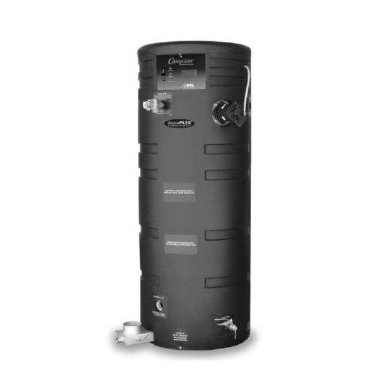
® CONQUEST WATER HEATER PRODUCT DESCRIPTION Component, Controls and Connection Locations (Locations May Vary) PV500-70 10/15... -
Page 8: Water Heater Installation
® CONQUEST WATER HEATER WATER HEATER INSTALLATION 3.1 Checking Equipment Before You Install • Inspect the unit completely upon receipt from the freight carrier before signing the bill of lading. Inspect the appliance and all accompanying parts for signs of impact or mishandling. Verify the total number of pieces shown on packing slips with those actually received. -
Page 9: Clearances To Combustible Surfaces
® CONQUEST WATER HEATER 3.5 Clearances To Combustible Surfaces The minimum clearance to combustible material is 15" from the top, 24" from the front and zero clearance (0") from the sides and back of the water heater. The Conquest can be installed directly on a combustible floor. Distance minimale aux matériaux combustibles est égale à... -
Page 10: General Piping Guidelines
® CONQUEST WATER HEATER GENERAL PIPING GUIDELINES 4.1 Inlet and Outlet Connections 1. Use only non-ferrous water piping and fittings. Do not use galvanized pipe or fittings. Use of ferrous or galvanized pipe or fittings can cause rust to form. 2. - Page 11 ® CONQUEST WATER HEATER SINGLE STORAGE WATER HEATER WITH SUPPLEMENTAL STORAGE TANK TWO WATER HEATERS WITH REVERSE RETURN PIPING PV500-70 10/15...
-
Page 12: Requirement For 180°F Delivered Water To A Dish Machine
® CONQUEST WATER HEATER 4.3 Requirement for 180°F Delivered Water to a Dish Machine When the Conquest water heater is applied as the high temperature water source for a dish washing application, the application requirements and notes below must be followed. Application Requirements and Notes: For Conquest applied as the high temperature water source for a dish washing application, follow all instructions in the “VENTING”... -
Page 13: Booster Heater Applications
® CONQUEST WATER HEATER 4.4 Booster Heater Applications When the Conquest water heater is applied as the high temperature water heater in a booster heater application, the application requirements and notes below must be followed. Application Requirements and Notes For Conquest applied in a booster heater application, follow all instructions in the “VENTING”, “GENERAL PIPING GUIDELINES”... - Page 14 ® CONQUEST WATER HEATER CONDENSATE DRAIN, TRAP & DISPOSAL All Conquest water heaters, except those applied as a booster water heater (see Section 4.3 for booster instructions), are for operation with normal cold inlet water temperatures of less than or equal 110°F and produce a significant amount of condensate.
-
Page 15: Condensate Neutralization System (Optional
® CONQUEST WATER HEATER 5.1 Condensate Neutralization System (optional) Condensate is only slightly acidic (3-5 PH), however this slight acidity can be neutralized by routing it through an optional PVI Condensate Neutralization System. Some “authorities having jurisdiction” require such neutralization before condensate disposal through a suitable drain. -
Page 16: Gas Supply And Piping
® CONQUEST WATER HEATER Condensate Trap with Optional Condensate Neutralizer Located Below Conquest GAS SUPPLY AND PIPING Verify the type of gas specified on rating plate is supplied to the unit. This unit is orificed for operation up to 2000 feet altitude. -
Page 17: Gas Piping Size
® CONQUEST WATER HEATER 6.5 Gas Piping Size Do not use the gas pipe connection size to determine the gas supply piping. Designing and sizing a gas supply piping system requires consideration of many factors and must be done by a gas supply piping expert. Always follow NFPA 54 National Fuel Gas Code for gas pipe sizing and gas pipe system design. -
Page 18: Combustion And Ventilation Air
® CONQUEST WATER HEATER 6.7 Gas Connection 1. Safe operation of unit requires adequate gas supply with the required static and dynamic (flow) pressures. Actual piping selection depends on many variables that must be carefully considered by the gas piping system designer. 2. -
Page 19: Maximum Allowed Remote Combustion Air Inlet Length
® CONQUEST WATER HEATER WARNING: Adequate clean combustion air must be provided to the appliance. The appliance must never operate under a negative pressure. Particular care must be taken when exhaust fans, compressors, air handling units, etc. may rob air from the appliance. The combustion air supply must be completely free of any chemicals or fumes, which may be corrosive to the appliance. -
Page 20: Remote Combustion Air Cap
® CONQUEST WATER HEATER 7.3 Remote Combustion Air Cap A suitable remote air termination must be used to prevent water, debris, animals or obstructing material from entering the remote air supply. 7.4 Vertical or Horizontal Remote Air Duct Termination • Air inlet must be located no less than 3 feet (0.91m) below the exhaust terminal if they are within 10 feet (3.05 m) of each other, unless the flue outlet terminates with a straight discharge. -
Page 21: Venting The Conquest
® CONQUEST WATER HEATER VENTING 8.1 Venting the CONQUEST: All Conquest models use the positive pressure generated by the burner system blower to push combustion products out of the vent. Since the vent system is under positive pressure and must be capable of containing condensate, it must be constructed of schedule 40 solid PVC or CPVC pipe. - Page 22 ® CONQUEST WATER HEATER Testing for leaks – Once the vent system is installed, it must be checked to confirm all joints in the vent system are air and water tight. After the vent is assembled, close the end of the vent with a taped plastic bag or some other temporary closure.
-
Page 23: Vertical Or Horizontal Vent Termination
® CONQUEST WATER HEATER The following vent information is provided for use in design calculations, if needed. Venting Specifications Max Vent Combustion Air Input MBtu/h Volume (cfm) Press. Inch W.C. 8.3 Vertical or Horizontal Vent Termination: 1. The vent terminal must have a minimum clearance of 4 feet (1.22 m) horizontally from, and in no case be located above or below, unless a 4 foot (1.22 m) horizontal distance is maintained from electric meters, gas meters, regulators and relief equipment. -
Page 24: Concentric Vent For Combustion Air And Exhausting Flue Products
® CONQUEST WATER HEATER WARNING: Do not connect multiple water heaters vents into a single unpowered or fixed speed powered vent. This could cause unsafe operation and the potential for poisonous carbon monoxide to enter occupied areas. Such improper installation can cause property damage, exposure to hazardous materials, personal injury or death. - Page 25 ® CONQUEST WATER HEATER The following information describes the components and installation methods for the IPEX System 636 Concentric Vent Termination Kit: ITEM NO. DESCRIPTON Wye-(Concentric) Rain Cap Exhaust Vent Pipe (Inner) Fresh Air Intake Pipe (Outer) Stainless Steel Screw & Nut Notes: •...
- Page 26 ® CONQUEST WATER HEATER Concentric Vent Kit Assembly, Installation and Support 1. Follow the concentric vent kit instructions to properly assemble the kit. 2. Follow the concentric vent kit instructions to locate and cut a hole in the roof or wall large enough to accommodate the largest dimension of the kit.
-
Page 27: Connecting To An Existing Vent System
® CONQUEST WATER HEATER Mechanically Fastened Rain Cap The Rain Cap must be installed with the supplied Stainless Steel screw and lock nut, and in accordance with instructions and diagram below. 1. Locate the drill location dimple on the outside of the rain cap. 2. -
Page 28: Cathodic Protection
® CONQUEST WATER HEATER WARNING: Do not plug the relief valve(s), use discharge piping smaller than the relief valve opening or install a reducing coupling, valve or other restriction in the relief valve discharge line. Failure to comply with these relief valve and discharge piping requirements can prevent the relief valve from providing its intended temperature and pressure protection, which can result in a sudden loss of pressure containment that can cause property damage, exposure to hazardous materials, personal injury or death. -
Page 29: Touch Screen User Interface
® CONQUEST WATER HEATER THE ELECTRONIC OPERATING SYSTEM (EOS) The Conquest EOS consists of three components: The Platform Ignition Module (PIM), plug-in ID card and the Control Display. The PIM is connected to the control display using an RJ485 patch cable. All communication between the PIM and control display as well as the power to the control display is through this cable. - Page 30 ® CONQUEST WATER HEATER 10.2 Status Field Display The Status Field displays the current operating status of the control display. Most items in the status field are only visible when in the View Menu or an alarm condition is present. Item Description Sanitation Mode is active.
- Page 31 ® CONQUEST WATER HEATER 10.4 View Menu (Home Screen - Default Display) Menu Icon The CTRL TEMP is the operating temperature sensed at the top of the tank Home Button. Return to the ‘Home’ Screen from any menu. Press and hold for 3 Home seconds to access the Button...
- Page 32 ® CONQUEST WATER HEATER 10.5 Control System Menus The control display has multiple access levels. System critical settings will not be available for adjustment. The settings which can be adjusted by the user will display UP and DOWN adjustment arrows on the right side of the display screen.
- Page 33 ® CONQUEST WATER HEATER 10.6 Changing The Operating Set Point (USER Level Access) The water Conquest water heater operates to satisfy the stored water temperature set point of the EOS control. The value of the controls’ set point is the desired stored tank water temperature. The unit ships with a factory set point of 120⁰F.
- Page 34 ® CONQUEST WATER HEATER 10.8 Scheduled Setback (USER Level Access) The SCHEDULE MENU allows the user to program this water heater to automatically lower the operating set point for times when a facility is not occupied or the use of hot water is curtailed. 1.
- Page 35 ® CONQUEST WATER HEATER 10.9 Using the Manual Override Menu (INSTaller Level Access) The OVERRIDE MENU is helpful during the initial commissioning as well as anytime burner adjustment is necessary. Manual override controls for the integral tank circulator and the optional SANI pump. 1.
- Page 36 ® CONQUEST WATER HEATER 2. The second screen will display the software revision for the touch panel display. Press the enter button to view. 3. The third screen allows the user to turn the display backlight ON continuously, OFF or TMPY will keep the backlight on only during use.
- Page 37 ® CONQUEST WATER HEATER The heater high limit temperature safety has exceeded its limit. This condition may HTR MAX be caused by a sensor failure or a faulty control board. Indicates a problem with the top temperature sensor, possibly a broken or shorted HTR TOP sensor wire or failed sensor.
- Page 38 ® CONQUEST WATER HEATER 11.8 ID Card The PIM determines its operating parameters by reading the identification code of an external plug-in ID card. The ID card is connected to the PIM at the J6 connector. Note: This ID card must be present for the PIM and appliance to operate. This card selects the proper settings in the PIM's memory for various appliance models.
- Page 39 ® CONQUEST WATER HEATER 12.1 EOS Register List Register Read/ Parameter Type Format Units Range Write Address 0=IDLE, 1=PREPurge, 2=IGNition, 3=BURNer Heater Ignition Read Input Enum on, 4=postPURG, 5=FAIL Upper Tank Temperature Read Input °F -22 to 266 Lower Tank Temperature Read Input °F...
- Page 40 ® CONQUEST WATER HEATER 12.2 Error Codes Code Description No Error Control Display Errors EEPROM Outdoor Sensor Supply Sensor DHW Sensor Vent Limiting FTBus Communication PIM Errors LWCO Remote Proof Air Pressure Low Gas Pressure Boiler Outlet/Tank Top Sensor Boiler Inlet/Tank Bottom Sensor Vent Sensor Hi-Limit Sensor Ignition Failure...
- Page 41 ® CONQUEST WATER HEATER REMOTE CONNECTIONS – TERMINAL STRIP 13.1 Making BMS/BAS remote connections for analog and binary (on/off) signals A terminal strip for the remote connection is located behind the bottom control panel door and is accessed removing the two thumb screws a lifting the hinged door. IMPORTANT: Do not use single strand bell wire for remote field connections to terminals R1-R2 and C1-C2.
- Page 42 ® CONQUEST WATER HEATER SEQUENCE OF OPERATION 1. Incoming 120VAC a. Full time power to the Fuse b. Full time power to the Main Control Switch 2. Power On - When the main control switch is turned on: a. 120V is applied to the step-down transformer (24V) b.
- Page 43 ® CONQUEST WATER HEATER 6. Ignition - When dwell time is completed a 4-second Trial for Ignition (TFI) period is initiated: a. The Gas Safety Valves are energized. b. The hot surface element is de-energized during the last second of the TFI period. c.
- Page 44 ® CONQUEST WATER HEATER INITIAL STARTUP 15.1 Initial Startup Requirements Installation must be complete prior to performing initial startup; and the startup must be complete prior to placing the water heater into service. Starting the water heater without proper piping, combustion air, venting or electrical connections or control settings can be dangerous and may void the product warranty.
- Page 45 ® CONQUEST WATER HEATER 2. Carefully study the burner start-up information included in this manual. 3. Fill system tank with water. a. Close the drain valve. b. Open a nearby hot water faucet(s) to allow trapped air to escape when filling the storage tank. Using the T&P valve alone will not allow the tank to completely fill.
- Page 46 ® CONQUEST WATER HEATER 17. If nothing happens, an error or failure message will display indicating that a control interlock or safety control did not satisfy. Some safety devices such as the Low Water Cut-off, Gas Pressure Switches and the High Temperature limit will require manual reset after lockout and therefore can be easily identified.
- Page 47 ® CONQUEST WATER HEATER NSF FOOD SERVICE INSTALLATION GUIDELINES All Conquest water heater models that have the Intertek ETL Sanitation mark on the information decal affixed to the front of the appliance are listed to NSF 5. This section provides additional information for architects, designers, and contractors in food service installations requiring compliance with NSF codes.
- Page 48 ® CONQUEST WATER HEATER 17.1 General Troubleshooting Symptom Probable Cause Corrective Action Power Supply Check fuse and/or circuit breaker. Check if On-Off switch is illuminated when on. If not check panel On-Off Switch fuse or incoming power. Temperature Control Check that the operating temperature control is set higher than the temperature of the water heater.
- Page 49 ® CONQUEST WATER HEATER 17.2 LED Error Code Listing The following table lists the errors detected by the Platform Ignition Module (PIM) control and the associated LED indications. Error Mode LED Code Recommended Troubleshooting Normal Operation Red LED Steady ON, Check that the proper ID card is securely connected.
-
Page 50: Replacement Parts
® CONQUEST WATER HEATER REPLACEMENT PARTS 18.1 Blower & Burner Assembly (Optional components may not be shown) ITEM DESCRIPTION 20 L 100A-GCL 25 L 100A-GCL 30 L 100A-GCL ASSY, AIR INTAKE ( Includes Brass ELL Hose Barb) 124161 124161 124161 ASSY, BULKHEAD AGC W/INSULATION 124160 124160... - Page 51 ® CONQUEST WATER HEATER 18.2 Control Panel Components ITEM DESCRIPTION 20 L 100A-GCL 25 L 100A-GCL 30 L 100A-GCL Digital Control Display HMI TEKMAR 126070 126070 126070 SWITCH, SPST N.C. MOMENTARY CONTACT SELECTA #SS229 70573 70573 70573 SWITCH, SPST N.O. MOMENTARY CONTACT SELECTA #SS228 75908 75908 75908...
- Page 52 ® CONQUEST WATER HEATER 18.3 Gas Train Assembly ITEM DESCRIPTION 20 L 100A-GCL 25 L 100A-GCL 30 L 100A-GCL VALVE, GAS 3/4 EBM #55290.04007 TYPE GB-ND 057 D01 S20 XP. 125504 125504 125504 VALVE, SHUTOFF 3/4 KEY GAS #216-242111 5336 5336 5336 UNION, BLACK 3/4...
- Page 53 ® CONQUEST WATER HEATER 18.4 Drain Valve – T & P Relief Valve – Integral Circulating Pump Assembly ITEM DESCRIPTION 20 L 100A-GCL 25 L 100A-GCL 30 L 100A-GCL FLANGE, MTG BRONZE INTEGRAL PUMP PL 2 SIDE RAD SB584 UNS CTD 122289 122289 122289...
- Page 54 ® CONQUEST WATER HEATER 18.6 Component Wiring and Conduit Routing Details PV500-70 10/15...
- Page 55 4, 5 & 6 below. 4. All gaskets on disassembled components must be replaced on reassembly with exact, Factory Authorized, ® replacement parts only. Gasket kits are available from your PVI Industries Representative or by contacting PVI ®...
- Page 56 11. All replacement parts are available through your PVI Industries Dealer. If you need assistance identifying or contacting your local dealer, you may contact PVI Industries, LLC directly at the address and telephone number located on the first and last page of this manual.
- Page 57 ® CONQUEST WATER HEATER RECOMMENDED MAINTENANCE SCHEDULE Regular service by a qualified service agency and routine maintenance must be performed to ensure safe, reliable and efficient operation. Yearly (Every 12 Months) Schedule annual service call by qualified service agency. 1. Check for piping leaks around pumps, relief valves, and tank connections. Repair, if found. 2.
- Page 58 ® CONQUEST WATER HEATER Requirements for the Commonwealth of Massachusetts: This equipment complies with Massachusetts State Fuel Gas and Plumbing Codes CMR 248 3.00-10.00 as amended. For all side wall horizontally vented gas fueled equipment installed in every dwelling, building or structure used in whole or in part for residential purposes, including those owned or operated by the Commonwealth and where the side wall exhaust vent termination is less than seven (7) feet above finished grade in the area of the venting, including but not limited to decks and porches, the following requirements shall be satisfied:...
- Page 59 ® CONQUEST WATER HEATER PV500-70 10/15...
- Page 60 Warranty Forms Ship Separately With Each Product MODEL NUMBER: SERIAL NUMBER: INSTALLATION DATE: ® , LLC • 3209 Galvez Ave. • Fort Worth, Texas 76111 • Phone 1-800-433-5654 • PVI INDUSTRIES www.pvi.com PV500-70 10/15...
Need help?
Do you have a question about the CONQUEST 20 L 100 A-GCL and is the answer not in the manual?
Questions and answers