Table of Contents
Advertisement
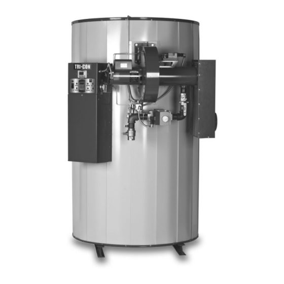
INSTALLATION & MAINTENANCE MANUAL
TRICON
WATER HEATER
MODELS (150, 180, 200) (L, SS) (250, 300) A-PVIF
Installation and service must be performed by a qualified service installer, service agency or the gas supplier.
THIS
MANUAL
CONTAINS
INFORMATION
REQUIRED
FOR
INSTALLATION,
OPERATION
AND
IMPORTANT:
MAINTENANCE OF THIS EQUIPMENT. READ AND FOLLOW THE INFORMATION IN THIS MANUAL AND ALL OTHER
PROVIDED INSTRUCTIONS, LABELS AND MARKINGS BEFORE INSTALLING, OPERATING OR SERVICING THIS UNIT.
TO THE INSTALLER: After installation, these instructions must be given to the equipment user or left near the appliance.
SPECIAL INSTRUCTIONS TO THE OWNER: Retain this manual for future reference. These instructions contain
important information that will help you in maintaining and operating this appliance.
PVI INDUSTRIES, LLC - Fort Worth, Texas 76111 - Web www.pvi.com - Phone 1-800-433-5654
1
PV500-47C 06/12
Advertisement
Table of Contents

Subscribe to Our Youtube Channel
Related Manuals for PVI Industries 150L-250 A-PVIF


Summary of Contents for PVI Industries 150L-250 A-PVIF
- Page 1 SPECIAL INSTRUCTIONS TO THE OWNER: Retain this manual for future reference. These instructions contain important information that will help you in maintaining and operating this appliance. PVI INDUSTRIES, LLC - Fort Worth, Texas 76111 - Web www.pvi.com - Phone 1-800-433-5654 PV500-47C 06/12 ...
-
Page 2: Table Of Contents
TABLE OF CONTENTS Safety Considerations Standard Features and Equipment Performance Pressure Vessel Heat Exchanger Code and Standards Burner, Operating Controls & Safeties Warranty and Service Policy (see warranty and service policy for details) Miscellaneous Product Descriptions Water Heater Installation Checking Equipment Before You Install Codes Electrical Requirements Handling and Location... - Page 3 Operating and Safety Controls 10.1 Temperature and Pressure Relief Valve(s) 10.2 Operating Temperature Control 10.3 High Water Temperature Limit Control 10.4 Cathodic Protection 10.5 Electronic Low Water Cut-off (optional) TEMPTRAC Electronic Controller Panel 11.1 Principal of Operation 11.2 Upper LED Readout 11.3 Lower LED Readout 11.4 Control Buttons 11.5 To View the Setpoint...
-
Page 4: Safety Considerations
SAFETY CONSIDERATIONS WARNING: If the information in the supplied manual(s) is not followed exactly, a fire, explosion or exposure to hazardous materials may result, causing property damage, personal injury or loss of life. FOR YOUR SAFETY Do not store or use gasoline or other flammable vapors or liquids in the vicinity of this or any other appliance. WHAT TO DO IF YOU SMELL GAS ... - Page 5 IMPORTANT SAFETY NOTE It takes only 5 seconds of skin contact with 140°F water to cause a second degree burn! You must protect against high water temperatures at all lavatories, tubs, showers and other points of hot water contact. Accidental scalding from high water temperatures is a greater risk in some types of installations.
-
Page 6: Standard Features And Equipment
STANDARD FEATURES AND EQUIPMENT Performance 87% thermal efficiency at full fire from 40° to 140°F Up to 92% thermal efficiency with modulation < 20 ppm NOx Ducts direct combustion air up to 100 equivalent feet through 6-inch diameter material (requires UL approved vent cap, see optional equipment list) ... -
Page 7: Product Descriptions
PRODUCT DESCRIPTION Component, Controls and Connection Locations (Locations May Vary) 250 SERIES PV500-47C 06/12 ... - Page 8 300 SERIES PV500-47C 06/12 ...
-
Page 9: Water Heater Installation
WATER HEATER INSTALLATION Checking Equipment Before You Install Inspect the unit completely upon receipt from the freight carrier before signing the bill of lading. Inspect the appliance and all accompanying parts for signs of impact or mishandling. Verify the total number of pieces shown on packing slips with those actually received. -
Page 10: Service Clearances
8. Do not install on carpet or other combustible floor coverings. If installation over a combustible floor is required, follow these guidelines: Use a base of hollow clay tile or concrete blocks from 8" to 12" thick and extending 24" beyond the sides. ... - Page 11 SINGLE WATER PIPING SINGLE STORAGE WATER HEATER WITH SUPPLEMENTAL STORAGE TANK PV500-47C 06/12 ...
-
Page 12: Condensate Drain, Trap & Disposal
TWO WATER HEATERS WITH REVERSE RETURN PIPING CONDENSATE DRAIN, TRAP & DISPOSAL The TRICON water heater is designed to produce significant amounts of condensate because of its high efficiency. Condensate occurs naturally when water vapor in combustion gases is cooled below the dew point. A 3/4” NPT drain connections is provided. -
Page 13: Condensate Neutralization System (Optional)
Condensate Piping and Trap with Optional Condensate Neutralizer Condensate Neutralization System (optional) Although only slightly acidic (3-5 PH), condensate can be routed through an optional Condensate Neutralization System (see image below) to become pH neutral allowing for disposal into any drain or sewer system without concern for corrosion. -
Page 14: Gas Supply And Piping
GAS SUPPLY AND PIPING Verify that the type of gas specified on rating plate is supplied to the unit. This unit is orificed for operation up to 2000 feet altitude. Appliance Btuh output derates 4% per 1000 feet elevation above sea level. Consult Factory for installations above 2000 feet elevation. -
Page 15: Appliance Isolation During Gas Supply Piping Pressure Test
MULTIPLE UNIT INSTALLATIONS GAS PIPING SIZE CHART Maximum Capacity of Pipe in Thousands of BTU’s per hour for gas pressures of 14 Inches Water Column (0.5 PSIG) or less and a pressure drop of 0.05 Inch Water Column (Based on NAT GAS, 1025BTU’s per Cubic Foot of Gas and 0.60 Specific Gravity). -
Page 16: Combustion And Ventilation Air
COMBUSTION AND VENTILATION AIR Provisions for adequate combustion and ventilation air to the mechanical room must be in accordance with Section 5.3 “Air for Combustion and Ventilation” of the latest edition of the National Fuel Gas Code, ANSI Z223.1 and/or CAN/CSA B149, Installation Codes or applicable provisions of the local building codes. -
Page 17: Remote Combustion Air Cap
A UL Listed air intake termination cap is available from PVI Industries and may have shipped with the water heater as a purchased option. 8.4 Vertical or Horizontal Remote Air Duct Termination ... -
Page 18: Venting
VENTING Venting the TRICON: TRICON models are designed for operation only with stainless steel venting listed by UL, ULC, ETL or CSA for Category IV, positive pressure, gas appliance venting. Follow the vent manufacturer’s instructions for installation, sealing, supporting and terminating their vent system. Do not use plastic venting of any type. Do not use a barometric damper with the TRICON positive pressure vent. -
Page 19: Vertical Or Horizontal Vent Termination
Vertical or Horizontal Vent Termination: 1. The vent terminal must have a minimum clearance of 4 feet (1.22 m) horizontally from, and in no case be located above or below, unless a 4 foot (1.22 m) horizontal distance is maintained from electric meters, gas meters, regulators and relief equipment. -
Page 20: Operating And Safety Controls
OPERATING AND SAFETY CONTROLS WARNING: Turn off all electrical service to the appliance when accessing the limit or other controls located inside the control cabinet. This cabinet contains High Voltage wiring and terminals. If the electrical service is not turned off and these terminals are touched, a dangerous shock causing personal injury or loss of life could occur. -
Page 21: Temptrac Electronic Controller Panel
TEMPTRAC™ ELECTRONIC CONTROLLER PANEL 11.1 Principle Of Operation The water heater operates to satisfy the setpoint of the TempTrac digital control whose sensor is located near the top of the water heater tank. Demand (flow) will typically create a drop in temperature, thus activating the water heater to add heat to the stored water. -
Page 22: To View The Setpoint
11.5 To View The Setpoint Push and release the SET key to see the set point value. To return to normal display, press SET + UP or wait 15 seconds without pressing any key. 11.6 To Change The Setpoint ... -
Page 23: Led Display Alarm Messages
11.8 LED Display Alarm Messages Alarm messages are displayed in the upper LED readout and alternate with the default display. An alarm LED ICON is also illuminated. (See TempTrac User Manual PV500-40 for full description.) ALARM RECOMMENDED CAUSE RESULTS OF ALARM CONDITION MESSAGE ACTION Inlet temperature sensor is not... -
Page 24: Sequence Of Operation
12.2 The Following Describes The Functions Of Each Of These Terminals And The Factory-Installed Options Required To Activate The Terminals: Note: Terminal P1-P2 are functional only when the water heater is equipped with the factory installed options required to activate the terminals. Terminals R1-R2, A1-A2, C1-C2 and T1-T2 are standard pre-wired functions on all models. - Page 25 4. Proof of Air Pressure Switch - The control will look for a signal from the airflow-proving switch, indicating that the blower is operating: a. When the airflow generated by the blower is sufficient to cause the differential air switch to close, the 15 - second pre-purge delay will start.
-
Page 26: Initial Startup
INITIAL STARTUP 14.1 Initial Startup Requirements Installation should be complete prior to performing initial startup; and the startup must be complete prior to placing the water heater into service. Starting the water heater without proper piping, combustion air, venting or electrical systems can be dangerous and may void the product warranty. - Page 27 b. Attach a manometer to measure the gas pressure at the manual gas shutoff valve located just upstream of the gas train. Adjust gas train inlet pressure to the specified value (e.g. 14" W.C.), and tightly close the gas train manual shutoff valve closest to the burner. c.
- Page 28 19. When the blower motor starts, the flame control will check for a positive air flow. If the air switch or blocked filter switch is not made the blower will stay on for a period of time then lockout. To adjust the air-proving switch, turn the adjustment screw counter-clockwise until the air proving light comes on, then turn the screw one turn counter-clockwise.
- Page 29 Gas Train Illustration (Optional components may not be shown) Alternate Gas Train Illustration (Optional components may not be shown) PV500-47C 06/12 ...
-
Page 30: Troubleshooting Guide
TROUBLESHOOTING GUIDE Problem Probable Cause Corrective Action Check fuse and/or circuit breaker. Check voltage at Power Supply 120/24V step-down transformer. On-Off Switch Check if On-Off switch is lighted Check that the operating temperature control is set Temperature Control higher than the temperature of the water heater. Check for bad ground or bad control. -
Page 31: Replacement Parts
REPLACEMENT PARTS REPLACEMENT PARTS PV500-47C 06/12 ... -
Page 32: Control Panel
16.1 Control Panel PV500-47C 06/12 ... -
Page 33: Control Panel Components
16.2 Control Panel Components (Optional components may not be included) Part No. Description Qty. 101947 CONTROL, HOT SURFACE IGNITION FENWAL CONTROL, TEMPERATURE TEMPTRAC DRIVE, VARIABLE FREQUENCY AC EMERSON 5613 FUSEHOLDER, PANEL TYPE #HTB-28I 5742 FUSE, MDA 15 AMP BUSS 250V NO SUBSTITUTE 113915 LWCO, PROTODESIGN #LW-3-C-1-A-03 58154... -
Page 34: Burner Assembly
16.3 Burner Assembly Optional components may or may not be shown PV500-47C 06/12 ... -
Page 35: Burner Assembly Components
16.4 Burner Assembly Components (Optional components may not be included) Item No. Qty. PVI Part No. Description BURNER ASSEMBLY COMPONENTS 117188 B&C, 2000 MBTU MXIF/PVIF 117189 ASSY, BURNER PVIF 2000M 113752 ASSY, BURNER TOP PLATE / RETURN TUBE 17 117190 ASSY, FILTER BOX 12 x 24 PVIF 117191 GAS / AIR FILTER TUBE... - Page 36 BURNER GAS TRAIN COMPONENTS 114530 PKG, GAS TRAIN 1 1/2 M x 3/8 P x 1 1/2 C 116921 REGULATOR, 1 1/2 MAXITROL #210EZ ZERO GOVERNOR 102836 VALVE, GAS DUNGS DMV-D 703/6 24VAC 5972 NIPPLE, BLACK 1/4 x 1 102838 FLANGE, BLACK 1 1/2 DUNGS 45327 VALVE, SHUTOFF 1 1/2 GAS COMBU...
-
Page 37: Periodic Maintenance
5 & 6 below. 4. All gaskets on disassembled components must be replaced on reassembly with exact, Factory Authorized, ® replacement parts only. Gasket kits are available from your PVI Industries Representative or by contacting PVI ®... - Page 38 11. All replacement parts are available through your PVI Industries Dealer. If you need assistance identifying or contacting your local dealer, you may contact PVI Industries, LLC directly at the address and telephone number located on the first and last page of this manual.
-
Page 39: Recommended Maintenance Schedule
RECOMMENDED MAINTENANCE SCHEDULE 1. Annual Maintenance a. Check all joints and pipe connections for tightness, corrosion or deterioration. b. Check the electronic-ignition system for quick ignition and a proper flame signal. c. Check all safety controls including thermostats for proper operation. d. - Page 40 ® , LLC 3209 Galvez Ave. Fort Worth, Texas 76111 Phone 1-800-433-5654 www.pvi.com PVI INDUSTRIES PV500-47C 06/12 ...
Need help?
Do you have a question about the 150L-250 A-PVIF and is the answer not in the manual?
Questions and answers
Goes through cycles till burner gas valve opens but does fire continues till lock out
The PVI Industries 150L-250 A-PVIF burner could cycle without firing until lockout due to the following potential causes:
1. Airflow-Proving Switch Issue: If the airflow generated by the blower is insufficient to close the differential air switch, the control will not proceed to the pre-purge stage, preventing ignition.
2. Blockages in Airflow or Burner Ports: Restricted combustion air or blockages (e.g., soot or debris) in burner ports can prevent proper operation.
3. Flame Rectification Problem: During the Trial for Ignition (TFI) period, if the flame safeguard control fails to detect a flame using flame rectification, the burner will not ignite.
4. Heat Exchanger Blockage: A blocked heat exchanger can restrict airflow or cause unsafe operation, preventing ignition.
5. Faulty Hot Surface Igniter: If the flame control determines that the proving current to the hot surface igniter does not meet the threshold, ignition will not proceed.
6. Gas Supply Issue: Excessive or insufficient gas supply can cause improper combustion or prevent ignition.
7. Improper Maintenance: Failure to replace gaskets or clean components properly during maintenance can lead to operational issues.
These issues should be addressed by a qualified service technician.
This answer is automatically generated