Advertisement
Quick Links
IMPORTANT:
READ AND FOLLOW THE INFORMATION IN THIS MANUAL, THE GENERAL
INSTALLATION & MAINTENANCE MANUAL, AND ALL OTHER PROVIDED INSTRUCTIONS,
LABELS AND MARKINGS BEFORE INSTALLING, OPERATING OR SERVICING THIS UNIT.
Typical Construction
Introduction
Start-up Procedures & Warnings
Electrical
Maintenance & Safety Inspections
MX Burner Manual, Start-up & Troubleshooting Guide
MXG Burner Manual
MXO Burner Manual
MXL Burner Manual
WARNING: If the information on the appliance and in the supplied manual(s) is not followed
exactly, a fire, explosion or exposure to hazardous materials may result causing
Do not store or use gasoline or other flammable vapors and liquids in the vicinity of this or any
other appliance.
Do not try to light any appliance.
Do not touch any electrical switch; do not use any phone in your building.
Immediately call your gas supplier from a neighbor's phone. Follow the gas supplier's
instructions.
If you cannot reach your gas supplier, call the fire department.
Installation and service must be performed by a qualified installer, service agency, or the gas
supplier.
This product contains, or may come to contain, materials that have been identified as carcinogenic,
or possibly carcinogenic, to humans. Before installing, servicing, or removing this product, read and
follow the supplied instructions.
PV500-17 07/13
INSTALLATION & MAINTENANCE MANUAL FOR
MAXIM
INTEGRATED WATER HEATING SYSTEM
TABLE OF CONTENTS
property damage, personal injury or loss of life.
FOR YOUR SAFETY
WHAT TO DO IF YOU SMELL GAS
PVI INDUSTRIES, LLC
3209 Galvez Ave.
Fort Worth, TX 76111
(800) 433-5654
www.pvi.com
Refer to PV500-21A
Refer to PV500-22A
Refer to Heat Wise SU-3
1
2
3
4 – 5
5
5 – 7
8 – 14
Section 17
Advertisement

Subscribe to Our Youtube Channel
Related Manuals for PVI Industries MAXIM


Summary of Contents for PVI Industries MAXIM
- Page 1 This product contains, or may come to contain, materials that have been identified as carcinogenic, or possibly carcinogenic, to humans. Before installing, servicing, or removing this product, read and follow the supplied instructions. PVI INDUSTRIES, LLC 3209 Galvez Ave. Fort Worth, TX 76111 (800) 433-5654 www.pvi.com...
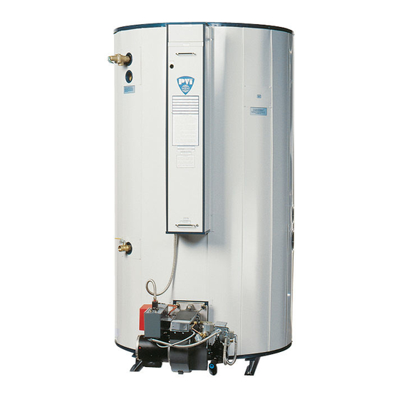
- Page 2 MAXIM INTEGRATED WATER HEATING SYSTEM TYPICAL CONSTRUCTION - MX MODEL FIGURE 17-1 1. VENT STACK * 8. HANDHOLE CLEANOUT 2. TEMPERATURE LIMITING DEVICE (set at 200°F) 9. UPPER OPERATING THERMOSTAT (set at 130°F) 3. OPERATING THERMOSTAT (set at 120°F) 10. COLD WATER INLET & RETURN CONNECTION 4.
-
Page 3: Precautionary Measures
MAXIM PRODUCT SAFETY INFORMATION REFRACTORY CERAMIC FIBER PRODUCT WITH CRYSTALLINE SILICA WARNING: This product contains crystalline silica which has been identified by the International Agency for Research on Cancer (IARC) as carcinogenic to humans. This product also contains refractory ceramic fibers which have been identified by the IARC as possibly carcinogenic to humans. -
Page 4: Start-Up Procedures
MAXIM START-UP PROCEDURES WARNING! This water heater is equipped with an bathtub or shower. Since the thermostat adjustable thermostat to control water temperature setting could be set too high, temperature. Hot water temperatures adjust the thermostat temperature setting required for automatic dishwasher and to 125°F or lower. - Page 5 MAXIM START-UP PROCEDURES (con't) CAUTION! Conduct the following gas train leakage test before start-up, at annual intervals and prior to investigating the cause of any reported occurrences of delayed ignition. 1. Using an appropriate bubble detection 3. Reattach the manometer to the gas train...
- Page 6 MAXIM MAINTENANCE AND SAFETY INSPECTIONS (con't) The tank will have a handhole for inspection IMPORTANT and cleaning. (See Figure 17-1, page 2.) To Condensate coming from the tubes on a cold inspect tank for scale buildup, remove the start is normal and does not indicate a leaking handhole cover.
- Page 7 MAXIM MAINTENANCE AND SAFETY INSPECTIONS (con’t) Instructions for Taking Water Heater Out of Service Extended shutdown of the appliance and C. Tag power switch(es) that fuel is off and tank restarting are as follows: is empty. A. Turn off all power and fuel supplies.
- Page 8 MAXIM AXIAL FLOW GAS BURNER CARBON MONOXIDE WARNING! CAUTION: IMPROPER COMBUSTION MAY CAUSE SERIOUS INJURY. PVI recommends a seasonal or annual combustion check-out be performed by a qualified service agency to ensure safe and efficient operation. TYPICAL CONSTRUCTION MX MODEL APPLICATION FIGURE 17-2 1.
- Page 9 MAXIM AXIAL FLOW GAS BURNER START-UP (Refer to Figure 17-2, page 8 to identify burner parts) 1. Remove the enclosure panel cover on the 7. With the electrodes exposed, check them water heater or boiler to expose the control for the proper settings as called for in circuit.
-
Page 10: Pressure Plate
MAXIM AXIAL FLOW GAS BURNER START-UP (continued) PRESSURE PLATE Set up and Tolerances Figure 17-3 13. Connect a test meter to the control for Record static pressure; it must not exceed reading the flame response signal. 14" W.C. Pressures above this could cause... - Page 11 MAXIM AXIAL FLOW GAS BURNER START-UP (continued) This section pertains to MEC120 control only. IMPORTANT When the blower motor starts, the air proving Where low gas pressure is a problem, special light on the MEC120 should be on. This arrangements may have been made to fire the indicates a positive airflow condition.
- Page 12 MAXIM AXIAL FLOW GAS BURNER START-UP (continued) 18. Check flue gases with a flue analyzer to Make sure the air shutter is locked make final settings of the air shutter. securely in place. a. The readings need to be taken from a 19.
- Page 13 MAXIM TROUBLESHOOTING SUGGESTIONS AXIAL FLOW GAS BURNER 1. BURNER FAILS TO START Defective On/Off switch. Replace switch. D. Occasional low voltage supply. Have local utility correct. Make certain the burner control A. Control circuit has an open control contact. circuit transformer (if supplied) is correct for the Check limits, low water cutoff, proof of closure voltage and power (VAC) being supplied.
- Page 14 MAXIM TROUBLESHOOTING SUGGESTIONS AXIAL FLOW GAS BURNER (continued) C. Defective automatic main or auxiliary gas shut C. Gas line obstructed. Check and correct. off valves. Check electrical circuitry to valves. Replace valves or correct circuitry as required. D. Gas train main and/or lead test cocks not fully open.
Need help?
Do you have a question about the MAXIM and is the answer not in the manual?
Questions and answers