Table of Contents
Advertisement
INSTALLATION & MAINTENANCE MANUAL
®
CONQUEST
WATER HEATER
MODELS (20, 25, 30) L 100 A-GCL
Installation and service must be performed by a qualified service installer, service agency or the gas supplier.
IMPORTANT:
THIS
MANUAL
CONTAINS
INFORMATION
REQUIRED
FOR
INSTALLATION,
OPERATION
AND
MAINTENANCE OF THIS EQUIPMENT. READ AND FOLLOW THE INFORMATION IN THIS MANUAL AND ALL OTHER
PROVIDED INSTRUCTIONS, LABELS AND MARKINGS BEFORE INSTALLING, OPERATING OR SERVICING THIS UNIT.
TO THE INSTALLER: After installation, these instructions must be given to the equipment user or left near the appliance.
SPECIAL INSTRUCTIONS TO THE OWNER: Retain this manual for future reference. These instructions contain
important information that will help you in maintaining and operating this appliance.
PVI INDUSTRIES, LLC - Fort Worth, Texas 76111 - Web
www.pvi.com
- Phone 1-800-433-5654
PV500-66 07/15
Advertisement
Table of Contents

Subscribe to Our Youtube Channel
Related Manuals for PVI Industries CONQUEST 20 L 100 A-GCL


Summary of Contents for PVI Industries CONQUEST 20 L 100 A-GCL
- Page 1 SPECIAL INSTRUCTIONS TO THE OWNER: Retain this manual for future reference. These instructions contain important information that will help you in maintaining and operating this appliance. PVI INDUSTRIES, LLC - Fort Worth, Texas 76111 - Web www.pvi.com - Phone 1-800-433-5654...
-
Page 2: Table Of Contents
® CONQUEST WATER HEATER TABLE OF CONTENTS Safety Considerations Product Description Water Heater Installation Checking Equipment Before You Install Codes Electrical Requirements Handling and Locating the Water Heater Clearances to Combustible Surfaces Service Clearances Other Codes and Regulatory Clearances and Requirements General Piping Guidelines Inlet and Outlet Connections Building Return Piping... - Page 3 ® CONQUEST WATER HEATER Operating and Safety Controls Temperature and Pressure Relief Valve(s) Cathodic Protection Electronic Low Water Cut-off Operating Temperature Control High Water Temperature Limit Control TEMPTRAC Electronic Controller Panel 10.1 Principal of Operation 10.2 Upper LED Readout 10.3 Lower LED Readout 10.4 Control Buttons 10.5 To View the Setpoint 10.6 To Change the Setpoint...
-
Page 4: Safety Considerations
® CONQUEST WATER HEATER SAFETY CONSIDERATIONS WARNING: If the information in the supplied manual(s) is not followed exactly, a fire, explosion or exposure to hazardous materials may result, causing property damage, personal injury or death. AVERTISSEMENT. Assurez-vous de bien suivre les instructions données dans cette notice pour réduire au minimum le risque d’incendie ou d’explosion ou pour éviter tout dommage matérial, toute blessure ou la mort FOR YOUR SAFETY •... - Page 5 ® CONQUEST WATER HEATER PRODUCT SAFETY INFORMATION REFRACTORY CERAMIC FIBER PRODUCT WITH CRYSTALLINE SILICA WARNING: This product contains or may come to contain crystalline silica, which has been identified by the International Agency for Research on Cancer (IARC) as carcinogenic to humans. This product also contains refractory ceramic fibers, which have been identified by the IARC as possibly carcinogenic to humans.
- Page 6 ® CONQUEST WATER HEATER IMPORTANT SAFETY NOTE It takes only 5 seconds of skin contact with 140°F water to cause a second degree burn! You must protect against high water temperatures at all lavatories, tubs, showers and other points of hot water contact. Accidental scalding from high water temperatures is a greater risk in some types of installations.
-
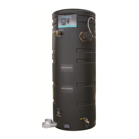
Page 7: Product Description
® CONQUEST WATER HEATER PRODUCT DESCRIPTION Component, Controls and Connection Locations (Locations May Vary) PV500-66 07/15... -
Page 8: Water Heater Installation
® CONQUEST WATER HEATER WATER HEATER INSTALLATION 3.1 Checking Equipment Before You Install • Inspect the unit completely upon receipt from the freight carrier before signing the bill of lading. Inspect the appliance and all accompanying parts for signs of impact or mishandling. Verify the total number of pieces shown on packing slips with those actually received. -
Page 9: Clearances To Combustible Surfaces
® CONQUEST WATER HEATER 8. Use the following diagram to locate anchors or attachment points, when connecting the heater to the floor. Typical concrete anchors: 5/16" x 1-3/4" double expansion shield 3.5 Clearances To Combustible Surfaces The minimum clearance to combustible material is 15" from the top, 24" from the front and zero clearance (0") from the sides and back of the water heater. -
Page 10: General Piping Guidelines
® CONQUEST WATER HEATER GENERAL PIPING GUIDELINES 4.1 Inlet and Outlet Connections 1. Use only non-ferrous water piping and fittings. Do not use galvanized pipe or fittings. Use of ferrous or galvanized pipe or fittings can cause rust to form. 2. - Page 11 ® CONQUEST WATER HEATER SINGLE STORAGE WATER HEATER WITH SUPPLEMENTAL STORAGE TANK TWO WATER HEATERS WITH REVERSE RETURN PIPING PV500-66 07/15...
-
Page 12: Condensate Drain, Trap & Disposal
® CONQUEST WATER HEATER CONDENSATE DRAIN, TRAP & DISPOSAL The Conquest water heater produces a significant amount of condensate. The condensate drain is under slightly positive flue pressure, so the provided 3/4" PVC condensate trap must always be used. This trap is sized and designed to fill with the proper amount of condensate to create a liquid barrier to prevent flue gases escaping through the condensate drain into the installed space. -
Page 13: Condensate Neutralization System (Optional
® CONQUEST WATER HEATER 5.1 Condensate Neutralization System (optional) Condensate is only slightly acidic (3-5 PH), however this slight acidity can be neutralized by routing it through an optional PVI Condensate Neutralization System. Some “authorities having jurisdiction” require such neutralization before condensate disposal through a suitable drain. -
Page 14: Gas Supply And Piping
® CONQUEST WATER HEATER Condensate Trap With Optional Condensate Neutralizer Located Below Conquest GAS SUPPLY AND PIPING Verify the type of gas specified on rating plate is supplied to the unit. This unit is orificed for operation up to 2000 feet altitude. -
Page 15: Gas Piping Size
® CONQUEST WATER HEATER 6.4 Manifold Pressure Measure at the pressure tap located downstream side of the manual valve closest to the burner. The rated manifold pressure appears on the product data label located near the front of the appliance. 6.5 Gas Piping Size Do not use the gas pipe connection size to determine the gas supply piping. -
Page 16: Appliance Isolation During Gas Supply Piping Pressure Test
® CONQUEST WATER HEATER 6.6 Appliance Isolation During Gas Supply Piping Pressure Test 1. The appliance and its provided manual shutoff valve must be disconnected from the gas supply piping system during any pressure testing of that system at test pressures in excess of ½ PSI (3.5 kPa). 2. -
Page 17: Combustion And Ventilation Air
® CONQUEST WATER HEATER COMBUSTION AND VENTILATION AIR Provisions for adequate combustion and ventilation air to the mechanical room must be in accordance with Section “Air for Combustion and Ventilation” in the latest edition of the NFPA 54 National Fuel Gas Code, ANSI Z223.1 and/or CAN/CSA B149, Installation Codes or applicable provisions of the local building codes. -
Page 18: Maximum Allowed Remote Combustion Air Inlet Length
® CONQUEST WATER HEATER 7.2 Maximum Allowed Remote Combustion Air Inlet Length (Equivalent Length) A vertical or horizontal remote air inlet system can be connected to this appliance without modification. The maximum length of field supplied single wall pipe, such as galvanized ventilation pipe, is shown in the chart below titled Maximum Air Inlet Duct Equivalent Length. -
Page 19: Combining Remote Air Ducting
® CONQUEST WATER HEATER Vertical Remote Air Horizontal Remote Air Notes: " * When flue outlet is terminated with a straight discharge, separation of terminations must be a minimum of 18 7.5 Combining Remote Air Ducting Each water heater MUST have separate intake piping, unless the air inlet piping, exhaust duct and other system considerations have been fully evaluated and a combined duct system designed by one of the duct design firms identified at www.pvi.com/vent-design.html. -
Page 20: Venting The Conquest
® CONQUEST WATER HEATER VENTING 8.1 Venting the CONQUEST: All Conquest models use the positive pressure generated by the burner system blower to push combustion products out of the vent. Since the vent system is under positive pressure and must be capable of containing condensate, it must be constructed of schedule 40 or 80 solid PVC or CPVC pipe. - Page 21 ® CONQUEST WATER HEATER Testing for leaks – Once the vent system is installed, it must be checked to confirm all joints in the vent system are air and water tight. After the vent is assembled, close the end of the vent with a taped plastic bag or some other temporary closure.
-
Page 22: Vertical Or Horizontal Vent Termination
® CONQUEST WATER HEATER The following vent information is provided for use in design calculations, if needed. Venting Specifications Max Vent Combustion Air Input MBtu/h Volume (cfm) Press. " W.C. 8.3 Vertical or Horizontal Vent Termination: 1. The vent terminal must have a minimum clearance of 4 feet (1.22 m) horizontally from, and in no case be located above or below, unless a 4 foot (1.22 m) horizontal distance is maintained from electric meters, gas meters, regulators and relief equipment. -
Page 23: Concentric Vent For Combustion Air And Exhausting Flue Products
® CONQUEST WATER HEATER Conventional Venting Through the Wall Venting Combining Vents with a Draft Inducer 8.5 Concentric Vent for Combustion Air and Exhausting Flue Products Concentric venting, to enable a single side wall or roof penetration for both combustion air and flue exhaust terminations, is available for the Conquest following the instructions located at www.pvi.com/vent-design.html. - Page 24 ® CONQUEST WATER HEATER WARNING: Do not plug the relief valve(s), use discharge piping smaller than the relief valve opening or install a reducing coupling, valve or other restriction in the relief valve discharge line. Failure to comply with these relief valve and discharge piping requirements can prevent the relief valve from providing its intended temperature and pressure protection, which can result in a sudden loss of pressure containment that can cause property damage, exposure to hazardous materials, personal injury or death.
- Page 25 ® CONQUEST WATER HEATER TEMPTRAC™ ELECTRONIC CONTROLLER PANEL 10.1 Principle Of Operation The water heater operates to satisfy the setpoint of the TempTrac digital control whose sensor is located near the top of the water heater tank. Demand (flow) will typically create a drop in temperature, thus activating the water heater to add heat to the stored water.
- Page 26 ® CONQUEST WATER HEATER 10.5 To View the Setpoint • Push and release the SET key to see the set point value. • To return to normal display, press SET + UP or wait 15 seconds without pressing any key. 10.6 To Change The Setpoint •...
-
Page 27: Led Display Alarm Messages
® CONQUEST WATER HEATER 10.8 LED Display Alarm Messages Alarm messages are displayed in the upper LED readout and alternate with the default display. An alarm LED ICON is also illuminated. ALARM RECOMMENDED CAUSE RESULTS OF ALARM CONDITION MESSAGE ACTION Inlet temperature sensor is not connected or is Check wiring and sensor “P1”... - Page 28 ® CONQUEST WATER HEATER REMOTE CONNECTIONS – TERMINAL STRIP 11.1 Making BMS/BAS remote connections for analog and binary (on/off) signals A terminal strip for the remote connection is located behind the bottom control panel door and is accessed removing the four thumb screws a lifting the hinged door. IMPORTANT: Do not use single strand bell wire for remote field connections to terminals R1-R2 and C1-C2.
- Page 29 ® CONQUEST WATER HEATER SEQUENCE OF OPERATION 1. Incoming 120VAC a. Full time power to the Fuse b. Full time power to the Main Control Switch 2. Power On - When the main control switch is turned on: a. 120V is applied to the step-down transformer (24V) b.
- Page 30 ® CONQUEST WATER HEATER Alarm on Any Failure a. When any safety device or remote proving interlock prevents the burner from firing within the allotted time period, once the call-for-heat is initiated, the TempTrac will initiate an alarm notification. This notification is indicated in the following ways: i.
- Page 31 ® CONQUEST WATER HEATER INITIAL STARTUP 13.1 Initial Startup Requirements Installation must be complete prior to performing initial startup; and the startup must be complete prior to placing the water heater into service. Starting the water heater without proper piping, combustion air, venting or electrical connections or control settings can be dangerous and may void the product warranty.
- Page 32 ® CONQUEST WATER HEATER b. Attach a manometer to measure the gas pressure at the manual gas shutoff valve located just upstream of the gas train. Adjust gas train inlet pressure to the specified value (e.g. 10.5" W.C.), and tightly close the gas train manual shutoff valve closest to the burner.
- Page 33 ® CONQUEST WATER HEATER 22. If the burner fails to light, the flame control will recycle two more times before lockout unless the Conquest contains the CSD-1 option. There is only a single try for ignition with the CSD-1 option. When lockout occurs, cycle the main power switch to reset the flame ignition control before the alarm-on-any-failure occurs.
- Page 34 ® CONQUEST WATER HEATER NSF FOOD SERVICE INSTALLATION GUIDELINES All Conquest water heater models that have the Intertek ETL Sanitation mark on the information decal affixed to the front of the appliance are listed to NSF 5-2009e. This section provides additional information for architects, designers, and contractors in food service installations requiring compliance with NSF codes.
-
Page 35: Troubleshooting Guide
® CONQUEST WATER HEATER TROUBLESHOOTING GUIDE Problem Probable Cause Corrective Action Power Supply Check fuse and/or circuit breaker. Check if On-Off switch is illuminated when on. If not check On-Off Switch panel fuse or incoming power. Check that the operating temperature control is set higher Temperature Control than the temperature of the water heater. - Page 36 ® CONQUEST WATER HEATER REPLACEMENT PARTS 16.1 Burner Assembly Burner Assembly Illustration for Models 20, 25, 30 (Optional components may not be shown) PV500-66 07/15...
- Page 37 ® CONQUEST WATER HEATER 16.2 Control Panel Enclosure Component Layout and Replacement PN’s LIST OF MATERIALS ITEM PART NO. DESCRIPTION CONTROL PANEL COMPONENTS 122644 TempTrac Control 199 – 300 MBtu/H 70573 Reset / Test Switch N.C. Momentary 122342 Indicating Light Main Decal 152249 Screw 10-24 X 1/2...
- Page 38 ® CONQUEST WATER HEATER 16.3 Component Wiring and Conduit Routing Details PV500-66 07/15...
- Page 39 4, 5 & 6 below. 4. All gaskets on disassembled components must be replaced on reassembly with exact, Factory Authorized, ® replacement parts only. Gasket kits are available from your PVI Industries Representative or by contacting PVI ®...
- Page 40 12. All replacement parts are available through your PVI Industries Dealer. If you need assistance identifying or contacting your local dealer, you may contact PVI Industries, LLC directly at the address and telephone number located on the first and last page of this manual.
- Page 41 ® CONQUEST WATER HEATER RECOMMENDED MAINTENANCE SCHEDULE Regular service by a qualified service agency and routine maintenance must be performed to ensure safe, reliable and efficient operation. Yearly (Every 12 Months) Schedule annual service call by qualified service agency. 1. Check for piping leaks around pumps, relief valves, and tank connections. Repair, if found. 2.
- Page 42 MODEL NUMBER: SERIAL NUMBER: INSTALLATION DATE: ® , LLC • 3209 Galvez Ave. • Fort Worth, Texas 76111 • Phone 1-800-433-5654 • PVI INDUSTRIES www.pvi.com PV500-66 07/15...
Need help?
Do you have a question about the CONQUEST 20 L 100 A-GCL and is the answer not in the manual?
Questions and answers