Table of Contents
Advertisement
INSTALLATION & MAINTENANCE MANUAL
Installation and service must be performed by a qualified service installer, service agency or the gas supplier.
IMPORTANT:
THIS
MANUAL
MAINTENANCE OF THIS EQUIPMENT. READ AND FOLLOW THE INFORMATION IN THIS MANUAL AND ALL OTHER
PROVIDED INSTRUCTIONS, LABELS AND MARKINGS BEFORE INSTALLING, OPERATING OR SERVICING THIS UNIT.
TO THE INSTALLER: After installation, these instructions must be given to the equipment user or left near the appliance.
SPECIAL INSTRUCTIONS TO THE OWNER: Retain this manual for future reference. These instructions contain
important information that will help you in maintaining and operating this appliance.
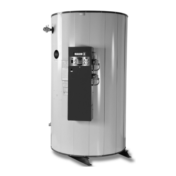
MAXIM 3
MODELS (40, 50, 75, 90, 100) L 125 A-MXIF
MODELS (50, 75, 90, 100) L (250, 300) A-MXIF
CONTAINS
INFORMATION
PVI INDUSTRIES, LLC - Fort Worth, Texas 76111 - Web www.pvi.com - Phone 1-800-433-5654
WATER HEATER
REQUIRED
FOR
INSTALLATION,
OPERATION
AND
PV500-50 08/14
Advertisement
Table of Contents

Subscribe to Our Youtube Channel
Related Manuals for PVI Industries 40L125A-MXIF


Summary of Contents for PVI Industries 40L125A-MXIF
- Page 1 SPECIAL INSTRUCTIONS TO THE OWNER: Retain this manual for future reference. These instructions contain important information that will help you in maintaining and operating this appliance. PVI INDUSTRIES, LLC - Fort Worth, Texas 76111 - Web www.pvi.com - Phone 1-800-433-5654 PV500-50 08/14...
-
Page 2: Table Of Contents
® MAXIM 3 WATER HEATER TABLE OF CONTENTS Safety Considerations Product Description Water Heater Installation Checking Equipment Before You Install Codes Electrical Requirements Handling and Location Service Clearances Clearances to Combustible Surfaces General Piping Guidelines Inlet and Outlet Connections Building Return Piping Gas Supply and Piping Gas Train and controls Certification Gas Control Trains... - Page 3 ® MAXIM 3 WATER HEATER TEMPTRAC Electronic Controller Panel Principal of Operation Upper LED Readout Lower LED Readout Control Buttons To View the Setpoint To Change the Setpoint To Change Other Parameters LED Display Alarm Messages Remote Connections – Terminal Strip 10.1 Making BMS/BAS Remote Connection for Analog and Binary Signals 10.2 Terminal Functions Sequence of Operation...
-
Page 4: Safety Considerations
® MAXIM 3 WATER HEATER SAFETY CONSIDERATIONS WARNING: If the information in the supplied manual(s) is not followed exactly, a fire, explosion or exposure to hazardous materials may result, causing property damage, personal injury or death. FOR YOUR SAFETY • Do not store or use gasoline or other flammable vapors or liquids in the vicinity of this or any other appliance. - Page 5 ® MAXIM 3 WATER HEATER IMPORTANT SAFETY NOTE It takes only 5 seconds of skin contact with 140°F water to cause a second degree burn! You must protect against high water temperatures at all lavatories, tubs, showers and other points of hot water contact. Accidental scalding from high water temperatures is a greater risk in some types of installations.
-
Page 6: Product Description
® MAXIM 3 WATER HEATER PRODUCT DESCRIPTION Component, Controls and Connection Locations (Locations and Connections May Vary) PV500-50 08/14... -
Page 7: Water Heater Installation
® MAXIM 3 WATER HEATER WATER HEATER INSTALLATION 3.1 Checking Equipment Before You Install Inspect the unit completely upon receipt from the freight carrier before signing the bill of lading. Inspect the appliance and all accompanying parts for signs of impact or mishandling. Verify the total number of pieces shown on packing slips with those actually received. -
Page 8: Service Clearances
® MAXIM 3 WATER HEATER 3.5 Service Clearances Allow sufficient space to provide adequate clearances on all sides for service and inspection. At least 24” above the water heater is required for filter replacement (if equipped) and burner/gas control service, 18” at left and right sides of the appliance. - Page 9 ® MAXIM 3 WATER HEATER WATER HEATER PIPING GUIDELINE One Water Heater – One Sidearm Storage Tank WATER HEATER PIPING GUIDELINE Two Water Heaters – Single Hot Outlet Temperature PV500-50 08/14...
-
Page 10: Gas Supply And Piping
® MAXIM 3 WATER HEATER GAS SUPPLY AND PIPING Verify that the type of gas specified on rating plate is supplied to the unit. This unit is orificed for operation up to 2000 feet altitude. Appliance Btuh output derates 4% per 1000 feet elevation above sea level. Consult Factory for installations above 2000 feet elevation. -
Page 11: Appliance Isolation During Gas Supply Piping Pressure Test
® MAXIM 3 WATER HEATER MULTIPLE UNIT INSTALLATIONS GAS PIPING SIZE CHART Maximum Capacity of Pipe in Thousands of BTU’s per hour for gas pressures of 14 Inches Water Column (0.5 PSIG) or less and a pressure drop of 0.05 Inch Water Column (Based on NAT GAS, 1025BTU’s per Cubic Foot of Gas and 0.60 Specific Gravity). -
Page 12: Combustion And Ventilation Air
® MAXIM 3 WATER HEATER COMBUSTION AND VENTILATION AIR Provisions for adequate combustion and ventilation air to the mechanical room must be in accordance with Section 5.3 “Air for Combustion and Ventilation” of the latest edition of the National Fuel Gas Code, ANSI Z223.1 and/or CAN/CSA B149, Installation Codes or applicable provisions of the local building codes. -
Page 13: Remote Combustion Air Cap
A UL Listed air intake termination cap is available from PVI Industries and may have shipped with the water heater as a purchased option. 6.4 Vertical or Horizontal Remote Air Duct Termination •... -
Page 14: Venting
(for attachment of the vent connector to the water heater vent connection) sized to match the required Category I vent diameter, must be obtained from PVI Industries. Attach the properly sized vent increaser to the water heater vent connection with three sheet metal screws. A properly installed and adjusted barometric damper helps stabilize draft and regulate high updraft. - Page 15 ® MAXIM 3 WATER HEATER • The vent cap must terminate at least 3 feet (0.91 m) above any forced air inlet within 10 feet (3.05 m); 4 feet (1.22 m) below, 4 feet (1.22 m) horizontally from or 1 foot (0.3 m) above any door, window or gravity air inlet to the building;...
-
Page 16: Maximum Category Iii Or Category Iv Venting Length
® MAXIM 3 WATER HEATER WARNING: Use only stainless steel venting listed by a nationally recognized testing laboratory for Category III or Category IV, positive pressure, gas appliance venting. Use of plastic pipe of any type or use of venting material other than specified in these instructions can result in failure of the venting system and/or exposure to carbon monoxide, which can result in property damage, personal injury or death. -
Page 17: Vertical Or Horizontal Vent Termination
® MAXIM 3 WATER HEATER 7.3.2 Vertical or Horizontal Vent Termination 1. The vent terminal must have a minimum clearance of 4 feet (1.22 m) horizontally from, and in no case be located above or below, electric meters, gas meters, regulators and relief equipment. 2. -
Page 18: Operating And Safety Controls
® MAXIM 3 WATER HEATER OPERATING AND SAFETY CONTROLS WARNING: Turn off all electrical service to the appliance when accessing the limit or other controls located inside the control cabinet. This cabinet contains High Voltage wiring and terminals. If the electrical service is not turned off and these terminals are touched, a dangerous shock causing personal injury or death could occur. - Page 19 ® MAXIM 3 WATER HEATER TEMPTRAC™ ELECTRONIC CONTROLLER PANEL 9.1 Principle Of Operation The water heater operates to satisfy the setpoint of the TempTrac digital control whose sensor is located near the top of the water heater tank. Demand (flow) will typically create a drop in temperature, thus activating the water heater to add heat to the stored water.
- Page 20 ® MAXIM 3 WATER HEATER 9.5 To View The Setpoint • Push and release the SET key to see the set point value. • To return to normal display, press SET + UP or wait 15 seconds without pressing any key. 9.6 To Change The Setpoint •...
- Page 21 ® MAXIM 3 WATER HEATER 9.8 LED Display Alarm Messages Alarm messages are displayed in the upper LED readout and alternate with the default display. An alarm LED ICON is also illuminated. (See TempTrac User Manual PV500-40 for full description.) ALARM RECOMMENDED CAUSE...
- Page 22 ® MAXIM 3 WATER HEATER REMOTE CONNECTIONS – TERMINAL STRIP 10.1 Making BMS/BAS remote connections for analog and binary (on/off) signals A terminal strip for the remote connection is located behind the hinged control panel at the top of the cabinet and is accessed by removing the bottom cover and then removing the screws at the top of the hinged cover.
- Page 23 ® MAXIM 3 WATER HEATER SEQUENCE OF OPERATION 1. Incoming 120VAC a. Full time power to the Main Control Switch b. Full time power to the Variable Frequency Drive 2. Power On - When the main control switch is turned on: a.
- Page 24 ® MAXIM 3 WATER HEATER 8. Delay-On Relay - Once the Delay-On (Low Fire Hold) Relay has timed out, it energizes the Modulation Release Relay (SPDT) to enable the analog signal from the TempTrac to the VFD to regulate the speed of the blower. a.
- Page 25 ® MAXIM 3 WATER HEATER 12.3 Resources • Product Installation & Maintenance Manuals • Start-up Report with instructions • Local, State, & Federal Codes • Toll Free 24-Hour Technical Support: 1-800-433-5654 12.4 On Site Considerations • Electrical Supply in accordance with Nameplate Rating •...
- Page 26 When high fire combustion has been reached and combustion is within the proper range, return to low fire to confirm settings again. CAUTION: If at any point carbon monoxide is in excess of 300ppm, contact PVI Industries customer service for assistance.
- Page 27 ® MAXIM 3 WATER HEATER Gas Train Illustration for Models 40 through 50 (Optional components may not be shown) Gas Train Illustration for Models 65 through 100 (Optional components may not be shown) PV500-50 08/14...
- Page 28 ® MAXIM 3 WATER HEATER TROUBLESHOOTING GUIDE Problem Probable Cause Corrective Action Check fuse and/or circuit breaker. Check voltage at Power Supply 120/24V step-down transformer. On-Off Switch Check if On-Off switch is lighted Check that the operating temperature control is set Temperature Control higher than the temperature of the water heater.
-
Page 29: Replacement Parts
® MAXIM 3 WATER HEATER REPLACEMENT PARTS REPLACEMENT PARTS PV500-50 08/14... - Page 30 ® MAXIM 3 WATER HEATER 14.1 Control Panel PV500-50 08/14...
- Page 31 ® MAXIM 3 WATER HEATER 14.2 Control Panel Components (Optional components may not be included) Part No. Description Qty. 101947 CONTROL, HOT SURFACE IGNITION FENWAL CONTROL, TEMPERATURE TEMPTRAC DRIVE, VARIABLE FREQUENCY AC EMERSON 5613 FUSEHOLDER, PANEL TYPE #HTB-28I 5742 FUSE, MDA 15 AMP BUSS 250V NO SUBSTITUTE 113915 LWCO, PROTODESIGN #LW-3-C-1-A-03 58154...
- Page 32 ® MAXIM 3 WATER HEATER 14.3 Burner Assembly Optional components may or may not be shown PV500-50 08/14...
- Page 33 ® MAXIM 3 WATER HEATER 14.4 Burner Assembly Components (Optional components may not be included) Item No. Qty. PVI Part No. Description 111876 BLOWER, FASCO #70430069 ASSY, BULKHEAD REFRACTORY BURNER, METAL PUNCHED 114513 SPACER, NYLON 1/4 ID X 1/2 OD X 11/16 MCMASTER C 115248 ASSY, INTAKE GAS AIR 7 OD X 1 NPT 3494...
- Page 34 5 & 6 below. All gaskets on disassembled components must be replaced on reassembly with exact, Factory Authorized, ® replacement parts only. Gasket kits are available from your PVI Industries Representative or by contacting ®...
- Page 35 All replacement parts are available through your PVI Industries Dealer. If you need assistance identifying or contacting your local dealer, you may contact PVI Industries, LLC directly at the address and telephone number located on the first and last page of this manual.
- Page 36 ® MAXIM 3 WATER HEATER RECOMMENDED MAINTENANCE SCHEDULE Annual Maintenance a. Check all joints and pipe connections for tightness, corrosion or deterioration. b. Check the electronic-ignition system for quick ignition and a proper flame signal. c. Check all safety controls including thermostats for proper operation. d.
- Page 37 ® MAXIM 3 WATER HEATER NOTES: PV500-50 08/14...
- Page 38 ® MAXIM 3 WATER HEATER MODEL NUMBER: SERIAL NUMBER: INSTALLATION DATE: ® , LLC • 3209 Galvez Ave. • Fort Worth, Texas 76111 • Phone 1-800-433-5654 • PVI INDUSTRIES www.pvi.com PV500-50 08/14...
Need help?
Do you have a question about the 40L125A-MXIF and is the answer not in the manual?
Questions and answers