Table of Contents
Advertisement
INSTALLATION & MAINTENANCE MANUAL
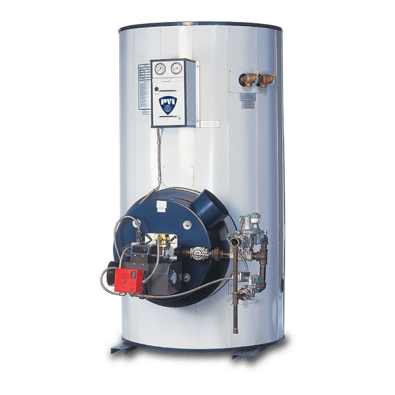
TURBOPOWER
MODELS: (742, 1485, 2228, 2971) N, P, L, SS (330, 425, 600, 950, 1200) A-TP
Installation and service must be performed by a qualified service installer, service agency or the gas supplier.
IMPORTANT: THIS MANUAL CONTAINS INFORMATION REQUIRED FOR INSTALLATION, OPERATION AND
MAINTENANCE OF THIS EQUIPMENT. READ AND FOLLOW THE INFORMATION IN THIS MANUAL AND ALL OTHER
PROVIDED INSTRUCTIONS, LABELS AND MARKINGS BEFORE INSTALLING, OPERATING OR SERVICING THIS UNIT.
TO THE INSTALLER:
After installation, these instructions must be given to the equipment user or left near the appliance.
SPECIAL INSTRUCTIONS TO THE OWNER:
information that will help you in maintaining and operating this appliance.
®
99
GAS WATER HEATER
Retain this manual for future reference. These instructions contain important
PVI INDUSTRIES, LLC - Fort Worth, Texas 76111 - www.pvi.com - Phone 1-800-433-5654
1
PV500-12 05/13
Advertisement
Table of Contents

Related Manuals for PVI Industries TURBOPOWER 99


Summary of Contents for PVI Industries TURBOPOWER 99
- Page 1 SPECIAL INSTRUCTIONS TO THE OWNER: Retain this manual for future reference. These instructions contain important information that will help you in maintaining and operating this appliance. PVI INDUSTRIES, LLC - Fort Worth, Texas 76111 - www.pvi.com - Phone 1-800-433-5654 PV500-12 05/13...
-
Page 2: Table Of Contents
TURBOPOWER 99 WATER HEATER TABLE OF CONTENTS Safety Considerations Product Descriptions Standard Features and Equipment Warranty Water Heater Installation Checking Equipment Before You Install Codes Electrical Requirements Location Installation Service Clearances Clearances to Combustible Surfaces Condensate Neutralization & Disposal... -
Page 3: Safety Considerations
TURBOPOWER 99 WATER HEATER SAFETY CONSIDERATIONS WARNING: If the information in the supplied manual(s) is not followed exactly, a fire, explosion or exposure to hazardous materials may result, causing property damage, personal injury or loss of life. FOR YOUR SAFETY ... - Page 4 TURBOPOWER 99 WATER HEATER IMPORTANT SAFETY NOTE It takes only 5 seconds of skin contact with 140°F water to cause a second degree burn! You must protect against high water temperatures at all lavatories, tubs, showers and other points of hot water contact.
-
Page 5: Product Descriptions
TURBOPOWER 99 WATER HEATER PRODUCT DESCRIPTION Flue stack * Burner Fixed temperature high limit device Upper flue collector Adjustable temperature limit device Lower flue collector Digital operating temperature control Rear module access (optional on some models) Control switch(s) and fuse(s) -
Page 6: Standard Features And Equipment
TURBOPOWER 99 WATER HEATER STANDARD FEATURES AND EQUIPMENT 3.1 Warranty Factory warranty does not cover improper installation or operation. (See warranty for complete details). Warranty exclusions include but are not limited to failure or malfunctions resulting from: Failures to properly apply, install, operate, or maintain the appliance in accordance to printed instructions. -
Page 7: Installation
TURBOPOWER 99 WATER HEATER 3. Place the appliance on a level, non-combustible floor. Concrete over wood is not considered non- combustible. 4. Do not install on carpet or other combustible floor coverings. 5. Installation over a combustible floor: Units installed over a combustible floor MUST be provided with a base of hollow clay tile or concrete blocks from 8"... -
Page 8: Combustion And Ventilation Air
TURBOPOWER 99 WATER HEATER CONDENSATION NEUTRALIZATION AND DISPOSAL ® The TURBOPOWER 99 condensing water heater will produce significant amounts of condensate because of its high efficiency. Condensate occurs naturally when water vapor in combustion gases is cooled below the dew point. -
Page 9: Vertical And Horizontal Remote Air
TURBOPOWER 99 WATER HEATER VERTICAL AND HORIZONTAL REMOTE AIR 7.1 Vertical or Horizontal Remote Air Option The vertical or horizontal remote air system requires a factory or site installed remote combustion air inlet option package. If your water heater does not include this optional equipment, contact your PVI sales representative to purchase the Remote Air Kit. -
Page 10: Venting Products Of Combustion
TURBOPOWER 99 WATER HEATER VENTING PRODUCTS OF COMBUSTION ® The TURBOPOWER 99 is designed for operation with a "positive pressure vent system" constructed of locally obtained 4” or 5" (or larger) schedule 40 or 80 solid PVC or CPVC pipe. Do not use PVC or CPVC pipe with cell/foam type construction (such as “CellCore”) or other non-solid PVC plastic pipe. -
Page 11: Horizontal And Vertical Venting Through A Wall Or Roof
TURBOPOWER 99 WATER HEATER 8.5 Horizontal and Vertical Venting Through a Wall or Roof Vent terminal locations, clearances, warnings and requirements stated in this manual apply, whether combustion air comes from the room or is ducted from outdoors. 1. The solid PVC or CPVC vent pipe must be sealed to the wall or roof at the point where it passes through the wall or roof. - Page 12 TURBOPOWER 99 WATER HEATER Horizontal Venting and Outside Combustion Air Follow all requirements in this manual and other instructions and markings for venting flue products to the outdoors, obtaining adequate combustion and ventilation air and general installation instructions. Vertical Venting and Outside Combustion Air Follow all requirements in this manual and other instructions and markings for venting flue products to the outdoors, obtaining adequate combustion and ventilation air and general installation instructions.
-
Page 13: Gas Supply And Piping
TURBOPOWER 99 WATER HEATER GAS SUPPLY AND PIPING Verify that the type of gas specified on rating plate is supplied to the unit. This unit is orificed for operation up to 2000 feet altitude. The appliance Btu/h output, like other similar equipment, derates approximately 4% per 1000 feet above sea level. -
Page 14: Appliance Isolation During Gas Supply Piping Pressure Test
TURBOPOWER 99 WATER HEATER MULTIPLE UNIT INSTALLATIONS GAS PIPING SIZE CHART Maximum Capacity of Pipe in Thousands of BTU’s per hour for gas pressures of 14 Inches Water Column (0.5 PSIG) or less and a pressure drop of 0.05 Inch Water Column (Based on NAT GAS, 1025BTU’s per Cubic Foot of Gas and 0.60 Specific Gravity). -
Page 15: General Information
TURBOPOWER 99 WATER HEATER GENERAL INFORMATION 10.1 Temperature and Pressure Relief Valve(s) Pipe the relief valve discharge to a suitable open drain. The drain pipe may not be smaller than the relief valve opening and must be secured to prevent it from lifting out of the drain under discharge pressure. Do not install valves or restrictions in the discharge line. -
Page 16: Temptrac Electronic Controller Panel
TURBOPOWER 99 WATER HEATER TEMPTRAC™ ELECTRONIC CONTROLLER PANEL 11.1 Principle Of Operation The water heater operates to satisfy the setpoint of the TempTrac digital control whose sensor is located near the top of the water heater tank. Demand (flow) will typically create a drop in temperature, thus activating the water heater to add heat to the stored water. -
Page 17: To View The Setpoint
TURBOPOWER 99 WATER HEATER 11.5 To View the Setpoint Push and release the SET key to see the set point value. To return to normal display, press SET + UP or wait 15 seconds without pressing any key. -
Page 18: Led Display Alarm Messages
TURBOPOWER 99 WATER HEATER 11.8 LED Display Alarm Messages Alarm messages are displayed in the upper LED readout and alternate with the default display. An alarm LED ICON is also illuminated. (See TempTrac User Manual PV500-40 for full description.) -
Page 19: Remote Connections - Terminal Strip
TURBOPOWER 99 WATER HEATER REMOTE CONNECTIONS – TERMINAL STRIP A terminal strip for the remote connection is located behind the hinged control panel at the top of the cabinet and is accessed by removing the bottom cover and then removing the screws at the top of the hinged cover. The... -
Page 20: Start-Up Procedure
TURBOPOWER 99 WATER HEATER START-UP PROCEDURE WARNING: You must connect the supplied gas train assembly to the burner union. Then connect the gas supply to the gas train. Do not connect the gas supply directly to this union. Failure to install the supplied gas train to the burner union before connecting the gas supply may result in uncontrolled gas flow into the appliance and/or the appliance area. -
Page 21: Periodic Maintenance
TURBOPOWER 99 WATER HEATER 18. If the burner fails to light, the flame control will lockout. When this happens press the reset button on the front of the control to recycle burner. 19. Once the main burner flame is established the firing rate will be controlled by the TempTrac control. -
Page 22: Diagrams
TURBOPOWER 99 WATER HEATER DIAGRAMS PV500-12 05/13... -
Page 23: Wiring Diagram
TURBOPOWER 99 WATER HEATER NOTES: 1. ALL FIELD WIRING MUST BE IN ACCORDANCE WITH THE REQUIREMENTS OF THE LOCAL CODES AND THE NATIONAL ELECTRICAL CODE, NFPA NO. 70, LATEST EDITION. 2. REMOVE JUMPER WHEN REMOTE PROVING INTERLOCK IS CONNECTED. - Page 24 TURBOPOWER 99 WATER HEATER Burner Diagram PV500-12 05/13...
- Page 25 TURBOPOWER 99 WATER HEATER MODEL NUMBER: SERIAL NUMBER: INSTALLATION DATE: PV500-12 05/13...
- Page 26 TURBOPOWER 99 WATER HEATER , LLC 3209 Galvez Ave. Fort Worth, Texas 76111 Phone 1-800-433-5654 www.pvi.com ® PVI INDUSTRIES PV500-12 05/13...
Need help?
Do you have a question about the TURBOPOWER 99 and is the answer not in the manual?
Questions and answers