Table of Contents
Advertisement
Quick Links
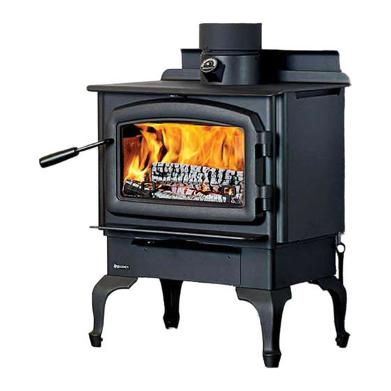
Cascades™ Series
Owners &
Installation Manual
Freestanding Woodstove
French Manual Download: https://bit.ly/2KaIHJB
www.regency-fire.com
Manuel en Français: https://bit.ly/2KaIHJB
MODEL: F1500
Tested by:
Installer: Please complete the details on the back cover
and leave this manual with the homeowner.
Homeowner: Please keep these instructions for future reference.
0219WS021S
919-665b
FPI FIREPLACE PRODUCTS INTERNATIONAL LTD. 6988 Venture St., Delta, BC Canada, V4G 1H4
07.15.19
Advertisement
Table of Contents

Related Manuals for Regency Fireplace Products Cascades F1500


Summary of Contents for Regency Fireplace Products Cascades F1500
- Page 1 Cascades™ Series Owners & Installation Manual Freestanding Woodstove French Manual Download: https://bit.ly/2KaIHJB www.regency-fire.com Manuel en Français: https://bit.ly/2KaIHJB MODEL: F1500 Tested by: Installer: Please complete the details on the back cover and leave this manual with the homeowner. Homeowner: Please keep these instructions for future reference. 0219WS021S 919-665b FPI FIREPLACE PRODUCTS INTERNATIONAL LTD.
- Page 2 Thank-you for purchasing a REGENCY FIREPLACE PRODUCT. The pride of workmanship that goes into each of our products will give you years of trouble-free enjoyment. Should you have any questions about your product that are not covered in this manual, please contact the REGENCY DEALER in your area. “This wood heater has a manufacturer set minimum low burn rate that must not be altered.
-
Page 3: Table Of Contents
table of contents Brick Flue Baffle Removal / Installation .........25 Copy of the Safety Label for F1500 .........4 Seasoned Firewood ...............26 Dimensions Operation Unit Dimensions ..............5 Operating Instructions ............26 Outside Air Dimensions ............5 Draft Control ................26 Installation Bypass Operating Handle ............26 Bypass Rod Replacement ............27 Modular Installation Options ...........6... -
Page 4: Copy Of The Safety Label For F1500
safety decal This is a copy of the label that accompanies each NOTE: Regency units are constantly being Regency Freestanding Woodstove (F1500). improved. Check the label on the unit and if We have printed a copy of the contents here there is a difference, the label on the unit is the for your review. -
Page 5: Dimensions
dimensions Unit Dimensions Unit with legs 20" 508mm " 441mm 24" " 610mm 165mm " 540mm Unit with pedestal 4-9/16" (115mm) Outside Air Dimensions Rear with pedestal with bottom heat shield + legs Front 4-15/16" (126mm) Rear 4-9/16" (115mm) Rear F1500 Regency Freestanding Woodstove Front... -
Page 6: Installation
installation Too tall a chimney may prompt excessive On pedestal units there are two locations where 1. Please read this entire manual before you install draft which can result in very short burn outside air may be adapted to the unit. If using and use your new woodstove. -
Page 7: Stove Assembly Prior To Installation
installation Stove Assembly Prior to Airmate Assembly for F1500 Rear Heat Deflector Installation Assembly for F1500 1) The airmate sits on top of the stove with the slots The F1500 unit requires the pedestal (or heat The rear heat deflector is supplied with the stove in the sides fitting over the curved deflector on shield and legs) to be attached to the base. -
Page 8: Pedestal Assembly Installation
installation Pedestal Assembly Installation Bottom Heat Shield and Legs Installation 1. For easier assembly, tip the stove on its back (onto a soft surface to prevent scratching) and The instructions below apply to the painted cast remove the front cover. leg. -
Page 9: Minimum Clearance To Combustible Materials
installation Minimum Clearance to Combustible Materials Please read the section below carefully as clearances depend on whether single wall or double wall pipe is installed on the stove. Measurements "From Unit" are from the top plate of the stove to a side wall or to a corner, and from the rear heat shield to a back wall. Clearances may only be reduced by means approved by the regulatory authority. -
Page 10: Minimum Alcove Clearance And Clearance To Combustible Materials
installation Minimum Alcove Clearance and Clearance to Combustible Materials The Regency Freestanding models have been alcove approved and must be installed with a listed double wall connector to the ceiling level. Single wall pipe (C Vent) is not approved for alcoves. Note: Minimum alcove ceiling height - 83"... -
Page 11: Floor Protection (Corner Installation)
installation Floor Protection (Corner Installation) A combustible floor must be protected by non-combustible material (like tile, concrete board, or certified to UL-1618 or as defined by local codes) extending beneath the heater and a minimum of 8" (203mm) from each side and minimum 16" (406mm)** from the front face of the stove and minimum 6"... -
Page 12: Step By Step Chimney And Connector Installation
installation Step by Step This stove may be connected to a lined masonry chimney or a listed factory built chimney suitable for 8. To complete your chimney installation, install Chimney and use with solid fuels and conforming to ULC629 in the double wall connector pipe from the Connector Installation Canada or UL-103HT in the USA. -
Page 13: Masonry Chimney
installation Masonry Chimney Ensure that a masonry chimney meets the mini- mum standards of the National Fire Protection Association (NFPA) by having it inspected by a professional. Make sure there are no cracks, loose mortar or other signs of deterioration and blockage. -
Page 14: Combustible Wall Chimney Connector Pass-Throughs
installation Combustible Wall Chimney Connector Pass-throughs Minimum chimney clearance to brick Method A: 12" (304.8 mm) Clearance to Combustible Wall Member: and combustibles 2 in. (50.8mm) Using a minimum thickness 3.5" (89 mm) brick and a 5/8" (15.9 mm) minimum wall thickness clay liner, construct a wall pass-through. Minimum clearance The clay liner must conform to ASTM C315 (Standard Specification 12 in. -
Page 15: Mobile Home Installation
installation Mobile Home Installation In addition to standard installation instructions the For Canadian Installations: see Outside Air following requirements are mandatory for installation Kit - Part # 846-502. in a mobile home. There are further requirements when installing this unit into a mobile home in Canada Only. 1. -
Page 16: Mobile Home Kit - For Canada
F1500 installation MOBILE HOME KIT - FOR CANADA Mobile Home Kit - for Canada Note: The optional ashdrawer cannot be used when using the Mobile Home Kit. Note: The optional ashdrawer cannot be used when using the Mobile Home Kit. 5. -
Page 17: Installing Outside Air From Pedestal Base
installation Installing Outside Air from Pedestal Base Installing Outside Air Using Bottom Heat Shield/ Legs If installing outside air from pedestal base, do not remove knock out from rear of pedestal. This must remain in place. Mobile Home Box Mobile Home Box Square Transition Box Blanking plate Collar... -
Page 18: Recommended Heights For Woodstove Flue
installation TABLE 1 Draft is the force which moves air from the appliance up MINIMUM RECOMMENDED FLUE HEIGHTS IN FEET through the chimney. The amount of draft in your chim- (Measured from the top of the unit) ney depends on the length of # OF ELBOWS the chimney, local geography, ELEVATION (FT) -
Page 19: Optional Outside Air Kit
installation Optional Outside Air Kit The Outside Air Kit is an option for Freestanding Stoves. Outside air for combustion can be brought in either through the bottom of the pedestal or through the rear plate of the pedestal. For both bottom and rear outside air the Pedestal Cover Plate must be installed. Loosen the 4 screws on the rear of the pedestal and slide the cover plate over them. -
Page 20: Brick Installation
installation Brick Installation Firebrick is included to extend the life of your stove and radiate heat more evenly. Check to see that all firebricks are in their correct positions and have not become misaligned during shipping. Install all firebricks (if bricks were removed at install) per the diagram below and place in their correct positions. Do not use a grate. -
Page 21: Removing Wooden Door Handle
installation Removing Wooden Glass Installation Handle Your Regency stove is supplied with 5 mm Neoceram ceramic glass that will withstand the highest heat that your unit will produce. In the event that you break your glass by impact, purchase your replacement from an authorized 1. -
Page 22: Wood Door And Handle Assembly
WOOD STOVES & INSERTS installation Wood Door & Handle Assembly WOOD DOOR & HANDLE ASSEMBLY Place the door onto the hinges and then place the door handle through the opening on the door, as shown in In preparation of installing the door handle, the nuts, Diagram 2. -
Page 23: Fan Installation
installation F1500 Fan Installation Fan assembly for use only with the room heater marked to indicate such use. FAN INSTALLATION FAN OPERATION (120V FAN) The fan is controlled by a rheostat which allows control of the heat 1. Remove the two screws from the top of the fan housing. output. -
Page 24: Stainless Steel Smoke Deflector Replacement
installation Stainless Steel Smoke Deflector adjustment / Replacement The stainless smoke deflector is located in the upper front area of the firebox. The deflector is held in place with 2 bolts Prior to the first fire, ensure deflector is seated properly and secured with 2 hand tightened bolts. Ensure deflector is seated so bolts are situated at the top of the keyhole before tightening. -
Page 25: Brick Flue Baffle Removal / Installation
installation Brick Flue Baffle 4. Install two smaller baffle pieces on either side. Removal / Installation Baffle side pieces The flue baffle system located in the upper area of the firebox is removable to make cleaning your chimney system easier. The brick baffle must be installed prior to your first fire. -
Page 26: Seasoned Firewood
operating instructions Seasoned Firewood Operating Bypass Operating Instructions Handle The F1500 is supplied with an air and bypass Whether you burn wood in a fireplace, stove or insert, With your unit now correctly installed and safety good quality firewood is the key to convenience, ef- operating handle. -
Page 27: Bypass Rod Replacement
installation bypass rod replacement If the bypass rod becomes damaged it will need to be replaced. 1. Allow the stove to burn out and cool down, until cool to touch. 2. Open the door and remove the following from inside the unit, smoke deflector, front air tube, baffles and catalyst. -
Page 28: First Fire
operating instructions First Fire 7. For the first few days, the stove will give off an 15. The controls of your unit or the air supply pas- odour from the paint. This is to be expected as sages should not be altered to increase firing the high temperature paint becomes seasoned. -
Page 29: Fan Operation
operating instructions Fan Operation Safety Guidelines Ash Drawer Operating Guidelines and Warnings Automatic 1. Only clean ashes out of the stove when the To operate the fan - turn on the rheostat. unit has cooled down. Remove the plug by CAUTION: Do not use chemicals for lifting on the handle using the tool provided. - Page 30 maintenance DO NOT BURN: CAUTION: DO NOT BURN GARBAGE 14. Do not store any fuel closer than 2 feet from • Treated wood OR FLAMMABLE LIQUIDS SUCH AS your unit. Do not place wood, paper, furniture, • Coal GASOLINE, NAPTHA OR ENGINE drapes or other combustibles near the appliance.
-
Page 31: Maintenance
maintenance Maintenance Creosote Door Gasket It is very important to carefully maintain your fire- When wood is burned slowly, it produces tar and If the door gasket requires replacement 7/8" diameter place stove, including burning seasoned wood and other organic vapours combine with moisture to material must be used. -
Page 32: Catalytic Combustor
maintenance Catalytic Combustor ACHIEVING AND MAINTAINING CATALYST LIGHT-OFF: Step 1: Light the stove in accordance with instructions within this manual. The temperature in the stove and the gases entering the combustor must be raised to between 500F to 700F for catalytic activity to be initiated. During Step 2: With smoke routed through the catalyst (by-pass closed) the start up of a cold stove a medium to high firing rate must be maintained go outside and observe the emissions leaving the chim-... -
Page 33: Combustor Assembly Removal / Replacement
maintenance Combustor Assembly 6. Remove the centre baffle. Removal / Replacement The catalytic thermometer on top of the stove should read in the active zone after the stove has been in operation for several hours. If the thermometer's indicator needle does not stay in the active zone, even with a hot fire, over a period of regular use, the catalyst may need to be cleaned. -
Page 34: Secondary Air Tube Removal / Installation
maintenance 3. Grasp secondary air tube firmly with vise grips, using a hammer tap vise NOTE: Replacement combustors can be retrieved from Applied Ceramics grips from right to left until air tube is released from grip. Remove. or contact your local Regency Dealer—see warranty information at the back of this manual for details. - Page 35 maintenance Annual Maintenance Completely clean out entire unit Annually Inspect air tube, Catalytic Combustor and bricks Replace any damaged parts. Adjust door catch assembly If unable to obtain a tight seal on the door - replace door gasket seal. Readjust door catch after new gasket installed. Inspect condition and seal of: Glass Gasket Door Gasket...
-
Page 36: Parts
parts list Main Assembly Part # Description 075-070 Left Side Heat Shield 075-071 Right Side Heat Shield 075-040 Side Baffle Cover (Each) 075-058F Draft Control Lever 075-052 Bracket Probe 815-557 Rear Air Deflector 075-955 Baffle Complete Set (Center + Sides) 033-953 3/4 OD x 19-1/4 Airtube 3 Per Unit (Each) 075-028... - Page 37 parts list Main Assembly F1500 Regency Freestanding Woodstove...
-
Page 38: Bottom Shield And Legs
parts list Bottom Shield and Legs part # description 075-911 Bottom heat Shield 850-126 Black Cast legs (Set Of 4) 850-128 Nickel Cast legs (Set Of 4) 075-914 Ashdrawer Bottom Heat Shield 942-110 Ashplug 820-249 Ashplug Tool 075-079 Blanking Plate 905-008 5/16"... -
Page 39: Complete Brick Kit
parts list 075-960 F1500S Complete Brick Kit Fire bricks Size 4-1/4" x 7" 4-1/2" x 7" 9" x 4-1/2" 9" x 2" 3-1/2" x 4-1/2" (AD) 4-1/4" x 8" 3-1/2" x 2-1/4" Ashdump brick F1500 Regency Freestanding Woodstove... -
Page 40: Catalyst Assembly
parts list Catalyst Assembly Part # Description 075-101 Catalyst slide 075-102 Gasket bracket 075-104 Long shield bracket 936-236 Rope gasket 1/2" diameter 075-043 Rod lock 075-531 5.83 diameter combustor assembly 075-044 Cat cradle 021-035 Offset flame shield 075-103 Rod clip lock F1500 Regency Freestanding Woodstove... - Page 41 Notes notes F1500 Regency Freestanding Woodstove...
-
Page 42: Warranty
warranty Limited Lifetime Warranty FPI Fireplace Products International Ltd. (for Canadian customers) and Fireplace Products U.S., Inc. (for U.S. customers) (collectively referred to herein as “FPI”) extends this Limited Lifetime Warranty to the original purchaser of this appliance provided the product remains in the original place of installation. The items covered by this limited warranty and the period of such coverage is set forth in the table below. - Page 43 warranty All warranty claims must be submitted by the dealer servicing the claim, including a copy of the Bill of Sale (proof of purchase by you). All claims must be complete and provide full details as requested by FPI to receive consideration for evaluation. Incomplete claims may be rejected.
- Page 44 warranty Limitations of Liability: The original purchaser’s exclusive remedy under this warranty, and FPI’s sole obligation under this warranty, express or implied, in contract or in tort, shall be limited to replacement, repair, or refund, as outlined above. IN NO EVENT WILL FPI BE LIABLE UNDER THIS WARRANTY FOR ANY INCIDENTAL OR CONSEQUENTIAL COMMERCIAL DAMAGES OR DAMAGES TO PROPERTY.
- Page 45 warranty Product Registration and Customer Support: Thank you for choosing a Regency Fireplace. Regency strives to be a world leader in the design, manufacture, and marketing of hearth products. To provide the best support for your product, we request that you complete a product registration form found on our Web Site under Customer Care within ninety (90) days of purchase.
-
Page 47: Catalytic Combustor Warranty Coverage
NO LABOR WILL APPLY. All warranty claims must be sent to: Regency Fireplace Products By Authorized Regency Dealer * Prices subject to change. - Page 48 notes Notes F1500 Regency Freestanding Woodstove...
- Page 49 Notes notes F1500 Regency Freestanding Woodstove...
- Page 50 notes Notes F1500 Regency Freestanding Woodstove...
- Page 51 F1500 Regency Freestanding Woodstove...
- Page 52 nstaller: Please complete the following information Dealer Name & Address: ______________________________________________ ___________________________________________________________________ Installer: ___________________________________________________________ Phone #: ___________________________________________________________ Date Installed: ______________________________________________________ Serial No.: __________________________________________________________ Printed in Canada Regency is a trademark of FPI Fireplace Products International Ltd. © Copyright 2019, FPI Fireplace Products International Ltd. All rights reserved.
Need help?
Do you have a question about the Cascades F1500 and is the answer not in the manual?
Questions and answers