Table of Contents
Advertisement
Quick Links
Advertisement
Table of Contents

Related Manuals for Supermicro X13SRN-H


Summary of Contents for Supermicro X13SRN-H
- Page 1 X13SRN-H/-E X13SRN-H/-E-WOHS USER’S MANUAL Revision 1.0...
- Page 2 State of California, USA. The State of California, County of Santa Clara shall be the exclusive venue for the resolution of any such disputes. Supermicro's total liability for all claims will not exceed the price paid for the hardware product.
- Page 3 About This Manual This manual is written for system integrators, IT technicians, and knowledgeable end users. It provides information for the installation and use of the X13SRN-H/-E series motherboard. About This Motherboard The X13SRN series motherboard is a 3.5" Single Board Computer (4.01" x 5.75") powered by the Intel®...
- Page 4 Note that this motherboard is intended to be installed and serviced by professional technicians only. For processor/memory updates, refer to our website at http://www.supermicro.com/ products/. Conventions Used in the Manual Special attention should be given to the following symbols for proper installation and to prevent...
- Page 5 Super X13SRN-H/-E User's Manual Contacting Supermicro Headquarters Address: Super Micro Computer, Inc. 980 Rock Ave. San Jose, CA 95131 U.S.A. Tel: +1 (408) 503-8000 Fax: +1 (408) 503-8008 Email: Marketing@supermicro.com (General Information) Sales-USA@supermicro.com (Sales Inquiries) Government_Sales-USA@supermicro.com (Gov. Sales Inquiries) Support@supermicro.com (Technical Support) RMA@supermicro.com...
-
Page 6: Table Of Contents
Preface Table of Contents Chapter 1 Introduction 1.1 Checklist ..........................9 Quick Reference .......................16 Quick Reference Table ......................17 Motherboard Features .......................18 1.2 Processor and Chipset Overview ..................23 1.3 Special Features ........................24 Recovery from AC Power Loss ..................24 1.4 System Health Monitoring ....................24 Onboard Voltage Monitors ....................24 Fan Status Monitor with Firmware Control ...............24 Environmental Temperature Control .................24... - Page 7 Super X13SRN-H/-E User's Manual 2.6 Connectors & Headers .......................37 Power Connections ......................37 Headers ..........................38 2.7 Jumper Settings .........................49 How Jumpers Work ......................49 2.8 LED Indicators ........................53 Chapter 3 Troubleshooting 3.1 Troubleshooting Procedures ....................54 Before Power On ......................54 No Power ..........................54 No Video ...........................55...
- Page 8 Preface Appendix A BIOS Codes A.1 BIOS POST Codes ......................104 Appendix B Software B.1 Microsoft Windows OS Installation ...................112 B.2 Driver Installation ......................114 B.3 SuperDoctor 5 .........................115 ® Appendix C Standardized Warning Statements Appendix D UEFI BIOS Recovery D.1 Overview ...........................119 D.2 Recovering the UEFI BIOS Image ...................119 D.3 Recovering the BIOS Block with a USB Device ..............120...
-
Page 9: Chapter 1 Introduction
Chapter 1 Introduction Congratulations on purchasing your computer motherboard from an industry leader. Supermicro boards are designed to provide you with the highest standards in quality and performance. In addition to the motherboard, several important parts that are included with the system are listed below. - Page 10 A secure data deletion tool designed to fully erase all data from storage devices can be found at our website: https://www.supermicro.com/about/policies/disclaimer.cfm?url=/wdl/ utility/Lot9_Secure_Data_Deletion_Utility/ • If you have any questions, contact our support team at: support@supermicro.com This manual may be periodically updated without notice. Check the Supermicro website for possible updates to the manual revision level.
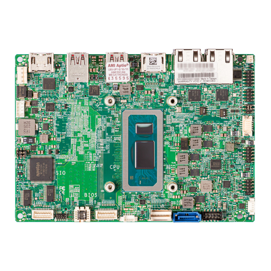
- Page 11 Chapter 1: Introduction Figure 1-1. X13SRN-H/-E Top Motherboard Image Figure 1-2. X13SRN-H/-E-WOHS Top Motherboard Image Note: All graphics shown in this manual were based upon the latest PCB revision available at the time of publication of the manual. The motherboard you received may...
- Page 12 Super X13SRN-H/-E User's Manual Figure 1-3. X13SRN-H/-E and X13SRN-H/-E-WOHS Bottom Motherboard Image Note: All graphics shown in this manual were based upon the latest PCB revision available at the time of publication of the manual. The motherboard you received may...
- Page 13 Chapter 1: Introduction Figure 1-4. X13SRN-H/-E and X13SRN-H/-E-WOHS Mechanical Drawings Top Mechanical Drawing D 10.00 D 3.25 95.20 95.20 85.80 83.64 70.00 70.00 65.38 65.25 38.18 37.29 17.81 17.81 17.69 6.05 0.00 0.00 146.00 Bottom Mechanical Drawing D3.25 D3.25 95.20 95.20...
- Page 14 Super X13SRN-H/-E User's Manual Figure 1-5. X13SRN-H/-E and X13SRN-H/-E-WOHS Mechanical Drawings X13SRN-H/-E Back Panel Mechanical Drawing X13SRN-H/-E-WOHS Back Panel Mechanical Drawing...
- Page 15 Chapter 1: Introduction Figure 1-6. Motherboard Layout (not drawn to scale) Top Layout JHDMI1 JHDMI2 USB6 USB4 FAN1 LAN2 LAN1 LED1 USB7 USB5 JPW1 JSIM1_OPT SRW2 SRW5 USB8 JPT1 USB0/1 SRW1 SRW4 USB2/3 JSPKR1 P1_PE2 4-0 COM1/COM2 COM3/COM4 I-SATA0 AUDIO FP JPH1 Bottom Layout JPME2...
-
Page 16: Quick Reference
Super X13SRN-H/-E User's Manual Quick Reference Top Layout USB6 USB4 LAN2 LAN1 JHDMI1 USB7 USB5 JHDMI2 FAN1 JHDMI1 JHDMI2 JPG1 USB6 USB4 FAN1 LAN2 LAN1 LED1 LED1 USB7 USB5 JPW1 JSIM1_OPT JPW1 JSIM1_OPT SRW5 SRW2 USB8 USB8 JPT1 JPT1 USB0/1... -
Page 17: Quick Reference Table
Chapter 1: Introduction Quick Reference Table Jumper Description Default Setting CMOS Clear Pins 1-3 (Normal) JPME2 Manufacturing Mode Pins 4-6 (Normal) Force Power On Pins 2-4 (Force power on) JPT1 TPM 2.0 Enable/Disable Pins 1-3 (Enable) SIM Detect Option Pins 2-4 (Low Active) JSIM1_OPT 5G/LTE USB/PCIe Option Pins 1-3 (USB) -
Page 18: Motherboard Features
DIMM Size • Up to 32 GB at 1.1 V Note: For the latest CPU/memory updates, refer to our website at http://www.supermicro.com/products/motherboard. Expansion Slots • One M.2 B-Key 2242/2280/3042 slot with a Nano SIM slot and support for SATA 6 Gb/s or PCIe 3.0 x1/USB 3.0/USB 2.0 •... - Page 19 Chapter 1: Introduction Motherboard Features I/O Devices • One HDMI 1.4b port on the rear I/O panel (supports up to 4K at 30 Hz) • HDMI Ports • One HDMI 2.0b port on the rear I/O panel (supports up to 4K at 60 Hz) •...
- Page 20 LED Indicators • Power/Suspend State LED indicator Environment • Operating Temperature Range: X13SRN-H/-E supports 0°C–60°C (32°F – 140°F) with active FAN and 0°C – 40°C with passive heatsink • Operating Temperature Range: X13SRN-H/-E-WOHS supports 0°C – 85°C (32°F – 185°F) •...
- Page 21 Chapter 1: Introduction Figure 1-7. SeriesSpecificationChart X13SRN-H/-E and X13SRN-H/-E-WOHS Base Freq Turbo Freq. Cores CPU TDP (Ghz) (Ghz) X13SRN Model Threads GFx EU Intel vPro P-core E-core P-core E-core P-core E-core X13SRN-H/ X13SRN-H-WOHS 1370P X13SRN-E/ X13SRN-E-WOHS 1350P Figure 1-8.
- Page 22 Super X13SRN-H/-E User's Manual Figure 1-9. System Block Diagram Note: This is a general block diagram and may not exactly represent the features on your motherboard. See the previous pages for the actual specifications of your moth- erboard.
-
Page 23: Processor And Chipset Overview
Chapter 1: Introduction 1.2 Processor and Chipset Overview Built with the Intel 13th Generation Core™ i7/i5 mobile processor series, the X13SRN-H/-E provides system performance, power efficiency, and feature sets to address the needs of next- generation computer users, and dramatically increases system performance for a multitude of server applications. -
Page 24: Special Features
Super X13SRN-H/-E User's Manual 1.3 Special Features Recovery from AC Power Loss The Basic I/O System (BIOS) provides a setting that determines how the system will respond when AC power is lost and then restored to the system. You can choose for the system to remain powered off, in which case you must press the power switch to turn it back on, or for it to automatically return to the power-on state. -
Page 25: Acpi Features
Windows operating systems. For detailed information regarding OS support, refer to the Supermicro website. 1.6 Power Supply As with all computer products, a stable power source is necessary for proper and reliable operation. -
Page 26: Chapter 2 Installation
Super X13SRN-H/-E User's Manual Chapter 2 Installation 2.1 Static-Sensitive Devices Electrostatic Discharge (ESD) can damage electronic com ponents. To avoid damaging your system board, it is important to handle it very carefully. The following measures are generally sufficient to protect your equipment from ESD. -
Page 27: Motherboard Installation
Chapter 2: Installation 2.2 Motherboard Installation All motherboards have standard mounting holes to fit different types of chassis. Make sure that the locations of all the mounting holes for both the motherboard and the chassis match. Although a chassis may have both plastic and metal mounting fasteners, metal ones are highly recommended because they ground the motherboard to the chassis. -
Page 28: Installing The Motherboard
Super X13SRN-H/-E User's Manual Installing the Motherboard 1. Install the I/O shield into the back of the chassis, if applicable. 2. Locate the mounting holes on the motherboard. See the previous page for the location. 3. Locate the matching mounting holes on the chassis. Align the mounting holes on the motherboard against the mounting holes on the chassis. -
Page 29: Memory Support And Installation
Memory Support The X13SRN-H/-E supports up to 64 GB of Non-ECC DDR5 SO-DIMM memory with speeds of up to 4800 MT/s in two memory slots on the bottom side of the motherboard. General Guidelines for Optimizing Memory Performance •... -
Page 30: So-Dimm Installation
Super X13SRN-H/-E User's Manual SO-DIMM Installation 1. Position the SO-DIMM module's bottom key so it aligns with the receptive point on the slot. Align 2. Insert the SO-DIMM module vertically at about a 45-degree angle. Press down until the module locks into place. -
Page 31: Rear I/O Ports
Chapter 2: Installation 2.4 Rear I/O Ports See Figure 2-1 below for the locations and descriptions of the various I/O ports on the rear of the motherboard. JHDMI1 JHDMI2 USB6 USB4 FAN1 LAN2 LAN1 LED1 USB7 USB5 JPW1 JSIM1_OPT SRW2 SRW5 USB8 JPT1... - Page 32 Super X13SRN-H/-E User's Manual HDMI Ports Two High Definition Multimedia Interface (HDMI) ports are on the back I/O panel. HDMI connectors are used to display both high definition video and digital sound through an HDMI- capable display with a single HDMI cable (not included). The HDMI port at JHDMI1 supports HDMI 2.0b, and the HDMI port at JHDMI2 supports HDMI 1.4b.
- Page 33 Chapter 2: Installation USB 3.2 Type-A ports, USB 3.2/DisplayPort 1.4 Alt Mode Type-C ports There are two USB 3.2 (10 Gb/s) Type-A ports (USB5, USB7) and two USB 3.2 (10 Gb/s)/ DisplayPort 1.4 Alt Mode Type-C ports (USB4, USB6) on the rear I/O panel. DisplayPort, developed by the VESA consortium, delivers digital display and fast refresh rate.
-
Page 34: Front Control Panel
Super X13SRN-H/-E User's Manual 2.5 Front Control Panel JF1 contains header pins for various buttons and indicators that are normally located on a control panel at the front of the chassis. These connectors are designed specifically for use with a custom chassis. Refer to the figure below for the descriptions of the front control panel buttons and LED indicators. - Page 35 Chapter 2: Installation Power Button The Power Button connection is located on pins 1 and 2 of JF1. Momentarily contacting both pins will power on/off the system. This button can also be configured to function as a suspend button with a setting in the BIOS – see Chapter 4. To turn off the power in the suspend mode, press the button for at least four seconds.
- Page 36 Super X13SRN-H/-E User's Manual HDD LED The HDD LED connection is located on pins 5 and 6 of JF1. Attach a cable to pin 6 to show hard drive activity status. Refer to the table below for pin definitions. HDD LED PinDefinitions(JF1)
-
Page 37: Connectors & Headers
Chapter 2: Installation 2.6 Connectors & Headers Power Connections 4-pin HDD Power Connector JPH1 is the 4-pin HDD power connector that provides power to hard disk drives. 4-pin HDD Power PinDefinitions Pins Definition 12 V Ground Ground 8-pin 12-24 V Main Power-in Connector JPW1 is the 12-24 V DC power connector that provides power to the motherboard. -
Page 38: Headers
Super X13SRN-H/-E User's Manual Headers Front Panel Audio Header (line-out, mic-in) A 10-pin front panel audio header located at AUDIO FP allows you to use the onboard sound for audio playback and input. Connect an audio cable to the header to use this feature. This header functions only between 0–60ºC. - Page 39 Chapter 2: Installation COMPortPinDefinitions COMPortPinDefinitions (COM1/COM2) (COM3/COM4) RS-422/485 RS-485 Pin# RS-232 Pin# RS-232 Full Duplex Half Duplex SP_DCD3 SP_DCD1 TX-1 Data-1 SP_DSR3 SP_DSR1 SP_RXD3 SP_RXD1 TX+1 Data+1 SP_RTS3 SP_RTS1 SP_TXD3 SP_TXD1 RX+1 SP_CTS3 SP_CTS1 SP_DTR3 SP_DTR1 RX-1 SP_RI3 SP_RI1 SP_DCD4 SP_DCD2 TX-2 Data-2...
- Page 40 Super X13SRN-H/-E User's Manual 8-bit GPIO Header One 8-bit General Purpose Input/Output (GPIO) header is located at JGP1.The GPIO header is a general purpose I/O expander on a pin header via the SMBus. Each pin can be configured to be an input pin or output pin in 2.54 mm pitch. The GPIO is controlled via the PCA9554APW 8-bit GPIO expansion from the PCH SMBus.
- Page 41 Chapter 2: Installation PCIe 4.0 x4 SlimSAS Connector There is one SlimSAS connector located at P1_PE2 4-0 to support one PCIe 4.0 x4 NVMe connection. This connector provide high-speed and low-latency connections via direct PCIe interfaces from the CPU to NVMe solid state drives (SSD). By simplifying driver/software requirements, this greatly increases SSD data-throughput performance and significantly reduces PCIe latency.
- Page 42 SATA ports provide serial-link signal connections, which are faster than legacy Parallel ATA. Note: For more information on the SATA HostRAID configuration, refer to the Intel SATA HostRAID user's guide posted at https://www.supermicro.com/support/manuals/. Front-accessible USB Headers The motherboard has two front-accessible USB 2.0 headers (USB0/1, USB2/3) and one USB 3.2 Type-C header.
- Page 43 Chapter 2: Installation Battery Cable Connector BT1 is a two-pin connector for an external CMOS battery. Refer to section 3.4 for battery installation instructions. This connector can also be used to clear the CMOS. To clear the CMOS, remove the battery, short pins 1-2 for more than 10 seconds, and then install the battery.
- Page 44 Super X13SRN-H/-E User's Manual M.2 Connectors This motherboard has three M.2 slots (M.2-B1, M.2-E1, M.2-M1). M.2 was formerly known as Next Generation Form Factor (NGFF) and serves to replace mini PCIe. M.2 allows for a variety of card sizes, increased functionality, and spatial efficiency. M.2-B1 supports an M.2 B-Key SATA 6 Gb/s or PCIe 3.0 x1/USB 3.0/USB 2.0 device in the 2242/2280/3042 form...
- Page 45 Chapter 2: Installation M.2 B-Key PinDefinitions(M.2-B1) Pin# Definition Pin# Definition P3V3SB P3V3SB FULL_CARD_POWER_OFF#(PU TO P1V8SB only) USB_D+ W_DISABLE1#(PU TO P3V3SB only) USB_D- LED_N KEY B KEY B KEY B KEY B KEY B KEY B KEY B KEY B PCIE_DIS VBUS_SENSE WAKE_ON_WWAN#(PU TO P1V8SB only) W_DISABLE2#(PU TO P1V8SB only)
- Page 46 Super X13SRN-H/-E User's Manual M.2 E-Key PinDefinitions(M.2-E1) Pin# Definition Pin# Definition P3V3SB USB_D+ P3V3SB USB_D- CNV_BT_I2S_SCLK CNV_WR_LANE1_DN CNV_RF_RESET_N CNV_WR_LANE1_DP CNV_BT_I2S_SDO MODEM_CLKREQ CNV_WR_LANE0_DN CNV_WR_LANE0_DP UART_BT_WAKE_N CNV_WR_CLK_DN CNV_BRI_RSP CNV_WR_CLK_DP KEY E KEY E KEY E KEY E KEY E KEY E KEY E...
- Page 47 Chapter 2: Installation M.2 M-Key PinDefinitions(M.2-M1) Pin# Definition Pin# Definition P3V3 P3V3 PERn3 PERp3 LED_N PETn3 P3V3 PETp3 P3V3 P3V3 PERn2 P3V3 PERp2 PETn2 PETp2 PERn1 PERp1 PETn1 PETp1 PERn0 PERp0 PETn0 PETp0 PERST# CLKREQ# REFCLKn REFCLKp KEY M KEY M KEY M KEY M KEY M...
- Page 48 Super X13SRN-H/-E User's Manual Nano SIM Connector The JSIM1 slot supports a Nano SIM card. SMBUS Header A System Management Bus header for additional slave devices or sensors is located at JSMBUS1 on the bottom side of the motherboard. SMBus Header PinDefinitions...
-
Page 49: Jumper Settings
Chapter 2: Installation 2.7 Jumper Settings How Jumpers Work To modify the operation of the motherboard, jumpers can be used to choose between optional settings. Jumpers create shorts between two pins to change the function of the connector. Pin 1 is identified with a square solder pad on the printed circuit board. See the diagram below for an example of jumping pins 1 and 2. - Page 50 Super X13SRN-H/-E User's Manual CMOS Clear Use JPME2 to clear CMOS, which clears all passwords. Before clearing the CMOS by closing pins 3-5, shut down the system. Manufacturing Mode Close pins 2-4 of jumper JPME2 to bypass SPI flash security and force the system to operate in the manufacturing mode, which will allow you to flash the system firmware from a host server for system setting modifications.
- Page 51 Chapter 2: Installation Force Power On Use JPT1 to select the Force power on function when the AC power cord is plugged in. When enabling force power on and AC power recovery, the system will boot up automatically without pressing the power button. Onboard TPM 2.0 Enable/Disable Use JPT1 to enable or disable support for the TPM module.
- Page 52 Super X13SRN-H/-E User's Manual SIM Detect Option Pins 2 and 4 on the JSIM1_OPT jumper are for SIM card detection. Since each SIM card vendor sets a different condition for detection, check with the vendor for the correct detection type and set the JSIM1_OPT jumper before installing the SIM card.
-
Page 53: Led Indicators
Chapter 2: Installation 2.8 LED Indicators Onboard Power LED LED1 is the Onboard Power LED. When this LED is on, the system is on. Be sure to turn off the system and unplug the power cord before removing or installing components. Refer to the table below for more information. -
Page 54: Chapter 3 Troubleshooting
Super X13SRN-H/-E User's Manual Chapter 3 Troubleshooting 3.1 Troubleshooting Procedures Use the following procedures to troubleshoot your system. If you have followed all of the procedures below and still need assistance, refer to the ‘Technical Support Procedures’ and/ or ‘Returning Merchandise for Service’ section(s) in this chapter. Always disconnect the AC power cord before adding, changing or installing any non hot-swap hardware components. -
Page 55: No Video
Chapter 3: Troubleshooting No Video 1. See if the Onboard Power LED at LED1 is green. If the LED is off, check the "No Power" section of this chapter. If the LED is red, check the "System Boot Failure" section of this chapter. 2. -
Page 56: Losing The System's Setup Configuration
Super X13SRN-H/-E User's Manual LosingtheSystem'sSetupConfiguration 1. Make sure that you are using a high-quality power supply. A poor-quality power supply may cause the system to lose the CMOS setup information. Refer to Section 1.6 for details on recommended power supplies. -
Page 57: Technical Support Procedures
Before contacting Technical Support, take the following steps. Also, note that as a motherboard manufacturer, Supermicro also sells motherboards through its channels, so it is best to first check with your distributor or reseller for troubleshooting services. They should know of any possible problems with the specific system configuration that was sold to you. -
Page 58: Frequently Asked Questions
3.3 Frequently Asked Questions Question: What type of memory does my motherboard support? Answer: The X13SRN-H/-E supports up to 64 GB of Non-ECC DDR5 SO-DIMM memory with speeds of up to 4800 MT/s in two memory slots. To enhance memory performance, do not mix memory modules of different speeds and sizes. -
Page 59: Battery Removal And Installation
Chapter 3: Troubleshooting 3.4 Battery Removal and Installation Battery Removal To remove the external CMOS battery, follow the steps below: 1. Power off your system and unplug your power cable. 2. Remove the battery cable at the BT1 connector on the board. 3. -
Page 60: Returning Merchandise For Service
Super X13SRN-H/-E User's Manual 3.5 Returning Merchandise for Service A receipt or copy of your invoice marked with the date of purchase is required before any warranty service will be rendered. You can obtain service by calling your vendor for a Returned Merchandise Authorization (RMA) number. -
Page 61: Chapter 4 Uefi Bios
Chapter 4: UEFI BIOS Chapter 4 UEFI BIOS 4.1 Introduction This chapter describes the AMIBIOS™ Setup utility for the motherboard. The BIOS is stored on a chip and can be easily upgraded using a flash program. Note: Due to periodic changes to the BIOS, some settings may have been added or deleted and might not yet be recorded in this manual. -
Page 62: Main Setup
Super X13SRN-H/-E User's Manual 4.2 Main Setup You will see the Main setup screen when you first enter the AMI BIOS setup utility. You can always return to the Main setup screen by selecting the Main tab on the top of the screen. - Page 63 Chapter 4: UEFI BIOS Memory Information Total Memory This feature displays the total size of memory available in the system.
-
Page 64: Advanced
Super X13SRN-H/-E User's Manual 4.3 Advanced Use the arrow keys to select the Advanced menu and press <Enter> to access the menu features. Warning: Take caution when changing the Advanced settings. An incorrect value, a very high DRAM frequency, or an incorrect DRAM timing setting may make the system unstable. When this occurs, revert to default manufacturer settings. - Page 65 Chapter 4: UEFI BIOS High Precision Event Timer Select Enabled to activate the High Precision Event Timer (HPET) that produces periodic interrupts at a much higher frequency than a Real-time Clock (RTC) does in synchronizing multimedia streams, providing smooth playback and reducing the dependency on other timestamp calculation devices, such as an x86 RDTSC Instruction embedded in the CPU.
- Page 66 Super X13SRN-H/-E User's Manual PowerConfiguration Watch Dog Function If enabled, the Watch Dog Timer will allow the system to reset or generate NMI based on jumper settings when it is expired for more than five minutes. The options are Disabled and Enabled.
- Page 67 Chapter 4: UEFI BIOS • Hyper Threading Technology • • SMX/TXT • 64-bit • EIST Technology • CPU C3 state • CPU C6 state • CPU C7 state • CPU C8 state • CPU C9 state • CPU C10 state •...
- Page 68 Super X13SRN-H/-E User's Manual Adjacent Cache Line Prefetch (Available when supported by the CPU) The CPU prefetches the cache line for 64 bytes if this feature is set to Disabled. The CPU prefetches both cache lines for 128 bytes as comprised if this feature is set to Enable. The options are Disabled and Enabled.
- Page 69 Chapter 4: UEFI BIOS Intel ® Speed Shift Technology Use this feature to enable or disable Intel Speed Shift Technology support. When this feature is enabled, the Collaborative Processor Performance Control (CPPC) version 2 interface will be available to control CPU P-States. The options are Disabled and Enabled. Turbo Mode Select Enable for processor cores to run faster than the frequency specified by the manufacturer.
- Page 70 Super X13SRN-H/-E User's Manual MonitorMWait Select Enabled to enable the Monitor/Mwait instructions. The Monitor instructions monitors a region of memory for writes, and MWait instructions instruct the CPU to stop until the monitored region begins to write. The options are Disabled and Enabled.
- Page 71 Chapter 4: UEFI BIOS Power Limit 1 Time Window Power Limit 1 Time Window value in seconds. This value defines how long Power Limit 1 may be exceeded. The CPU throttles to remain under Power Limit 1 when the duration of Power Limit 1 Time Window is exceeded.
- Page 72 Super X13SRN-H/-E User's Manual Memory Scrambler Use this feature to enable or disable memory scrambler support. The options are Dis- abled and Enabled. Force ColdReset Use this feature to enable or disable a cold boot during a MRC execution. The options are Enabled and Disabled.
- Page 73 Chapter 4: UEFI BIOS Internal Graphics Select Auto to enable internal graphics even when a device is installed on an expansion slot. The options are Auto, Disabled, and Enabled. GTT Size Use this feature to set the memory size to be used by the graphics translation table (GTT).
- Page 74 Super X13SRN-H/-E User's Manual DMI/OPIConfiguration DMI Gen3 ASPM Use this feature to set the Active State Power Management (ASPM) state on the System Agent (SA) side of the DMI Link. The options are Disabled, Auto, ASPM L0s, ASPM L1, and ASPM L0sL1.
- Page 75 Chapter 4: UEFI BIOS Maximum GT frequency Use this feature to define the Maximum GT frequency. Choose between 33 MHz (RPN) and 1200 Mhz (RP0). Any value beyond this range will be clipped to its min/max sup- ported by the CPU. The options are Default Max Frequency, 100Mhz, 150Mhz, 200Mhz, 250Mhz, 300Mhz, 350Mhz, 400Mhz, 450Mhz, 500Mhz, 550Mhz, 600Mhz, 650Mhz, 700Mhz, 750Mhz, 800Mhz, 850Mhz, 900Mhz, 950Mhz, 1000Mhz, 1050Mhz, 1100Mhz, 1150Mhz, and 1200Mhz.
- Page 76 Super X13SRN-H/-E User's Manual PCIe M.2-E1/PCIe M.2-B1 L1 Substates Use this feature to set the PCI Express L1 Substates. The options are Disabled, L1.1, and L1.1 & L1.2. PCIe M.2-E1/PCIe M.2-B1 PCIe Speed Use this feature to select the PCI Express port speed. The options are Auto, Gen1, Gen2, and Gen3.
- Page 77 Chapter 4: UEFI BIOS Boot Description Highlight the feature and press <Enter> to create a description. Boot URI Highlight the feature and press <Enter> to create a boot URI. Instance of Priority 2: Enter a value to set the rank target port. The default is 0. NCT6126DSuperIOConfiguration The following Super IO information will display: •...
- Page 78 Super X13SRN-H/-E User's Manual SerialPort4Configuration Serial Port 4 Use this feature to enable or disable serial port 4. The options are Disabled and Enabled. Device Settings The I/O and IRQ address for serial port 4 is IO=2E8h; IRQ=7;. NetworkConfiguration ...
- Page 79 Chapter 4: UEFI BIOS MAC:XXXXXXXXXXXX-IPv6NetworkConfiguration MAC:XXXXXXXXXXXX-IPv6NetworkConfiguration EnterConfigurationMenu Interface Name Interface Type MAC address Host addresses Route Table Gateway addresses DNS addresses Interface ID This feature shows the interface ID for the specified network device. DAD Transmit Count This feature sends Neighbor Solicitation messages while performing a Duplicate Address Detection (DAD) to make sure there is no IP address duplication.
- Page 80 Super X13SRN-H/-E User's Manual ME FW Image Re-Flash Use this feature to update the Management Engine firmware. The options are Disabled and Enabled. TPM Device Selection Use this feature to select dTPM or PTT for the TPM device. dTPM is discrete Trusted Platform Module and PTT is Platform Trusted Technology.
- Page 81 Chapter 4: UEFI BIOS OS Timer / BIOS Timer These options appear if Watch Dog (above) is enabled. This is a timed delay in seconds, before a system power down or reset after a BIOS or operating system failure is detected. Enter the value in seconds.
- Page 82 Super X13SRN-H/-E User's Manual RemotePlatformEraseConfiguration Enable Remote Platform Erase Feature Use this feature to enable or disable the Remote Platform Erase (RPE) feature for solid state drives. The options are Disabled and Enabled. SSD Erase Mode Select Real to securely erase a solid state drive through RPE. The options are Simu- lated and Real.
- Page 83 Chapter 4: UEFI BIOS Consistent Device Name Support This feature controls the device naming for network devices and slots. The options are Disabled and Enabled. PCIe/PCI/PnPConfiguration PCIe M.2-E1 OPROM Use this feature to select which firmware type to be loaded for the add-on card in this slot. The options are Disabled and EFI.
- Page 84 Super X13SRN-H/-E User's Manual I-SATA 0 / M.2-B1 This feature displays the information detected on the installed SATA drive on the particular SATA port. • Software Preserve Support Hot Plug Set this feature to Enable for hot plug support, which allows you to replace a SATA drive without shutting down the system.
- Page 85 Chapter 4: UEFI BIOS Serial Port Console Redirection COM1/2/3/4 Console Redirection Select Enabled to enable console redirection support for a serial port. The options are Enabled and Disabled. *If the feature above is set to Enabled, the following features are available for configuration: COM1/2/3/4 Console Redirection Settings Use this feature to specify how the host computer will exchange data with the client...
- Page 86 Super X13SRN-H/-E User's Manual COM1/2/3/4 Flow Control Use this feature to set the flow control for Console Redirection to prevent data loss caused by buffer overflow. Send a "Stop" signal to stop sending data when the receiving buffer is full. Send a "Start" signal to start sending data when the receiving buffer is empty. The options are None and Hardware RTS/CTS.
- Page 87 Chapter 4: UEFI BIOS AMT SOL Bits per second Use this feature to set the transmission speed for a serial port used in Console Redirection. Make sure that the same speed is used in the host computer and the client computer. A lower transmission speed may be required for long and busy lines.
- Page 88 Super X13SRN-H/-E User's Manual AMT SOL Putty KeyPad This feature selects Function Keys and KeyPad settings for Putty, which is a terminal emulator designed for the Windows OS. The options are VT100, LINUX, XTERMR6, SCO, ESCN, and VT400. AMT SOL Redirection After BIOS POST Use this feature to enable or disable legacy Console Redirection after BIOS POST.
- Page 89 Chapter 4: UEFI BIOS Flow Control Use this feature to set the flow control for Console Redirection to prevent data loss caused by buffer overflow. Send a "Stop" signal to stop sending data when the receiving buffer is full. Send a "Start" signal to start sending data when the receiving buffer is empty. The options are None, Hardware RTS/CTS, and Software Xon/Xoff.
- Page 90 Super X13SRN-H/-E User's Manual Intel(R) Ethernet Connection (3) I225-IT - XX:XX:XX:XX:XX:XX UEFI Driver Device Name PCI Device ID Link Status MAC Address TLSAuthenticationConfiguration This submenu allows you to configure Transport Layer Security (TLS) settings. ServerCAConfiguration EnrollCertification EnrollCertificationUsingFile Use this feature to enroll certification from a file.
- Page 91 Chapter 4: UEFI BIOS Intel(R) Ethernet Controller (3) I225-IT Intel(R) Gigabit 0.9.03 Controller 6C583E18 Child 0 Intel(R) Ethernet Controller (3) I225-IT COMPortModeConfiguration COM1/COM2 Mode Use this feature to select the COM1 mode. The settings are RS-232, RS-485/422 Full Duplex, and RS-485 Half Duplex.
-
Page 92: Event Logs
Super X13SRN-H/-E User's Manual 4.4 Event Logs Use this menu to configure Event Log settings. Change SMBIOS Event Log Settings Enabling/Disabling Options SMBIOS Event Log Change this feature to enable or disable all features of the SMBIOS Event Logging during system boot. - Page 93 Chapter 4: UEFI BIOS SMBIOS Event Log Standard Settings Log System Boot Event This option toggles the System Boot Event logging to enabled or disabled. The options are Disabled and Enabled. MECI The Multiple Event Count Increment (MECI) counter counts the number of occurences that a duplicate event must happen before the MECI counter is incremented.
-
Page 94: Thermal & Fan
Super X13SRN-H/-E User's Manual 4.5 Thermal & Fan Use this menu to view Thermal and Fan settings. Temperature • Peripheral Temperature • System Temperature • CPU Temperature • PCH Temperature Fan Speed • FAN1 Voltage • PVDD2 • P12V •... - Page 95 Chapter 4: UEFI BIOS • P3V3 • PVCCCORE • P1V8SB • P1V05_PROC Fan Control Fan Control Setting Fan Speed Control Mode Use this feature to select the fan speed control mode. The options are Quiet, Standard, and Full Speed.
-
Page 96: Security
Super X13SRN-H/-E User's Manual 4.6 Security Use this menu to configure the security settings for the system. Administrator Password Press <Enter> to create a new or change an existing Administrator password. Hard Drive Security Frozen Use this feature to enable or disable the BIOS security frozen command for SATA and NVMe devices. - Page 97 Chapter 4: UEFI BIOS Secure Boot Mode Use this feature to configure Secure Boot variables without authentication. The options are Standard and Custom. Enter Audit Mode Select this feature to enter the audit mode to configure PK. Key Management This submenu allows you to configure the following Key Management settings.
- Page 98 Super X13SRN-H/-E User's Manual Key Exchange Keys Use this feature to enter and configure a set of values to be used as Key-Exchange-Keys for the system. These values also indicate the sizes, keys numbers, and the sources of the authorized signatures. Select Update to update your "Key Exchange Keys." Select Append to append your "Key Exchange Keys."...
-
Page 99: Boot
Chapter 4: UEFI BIOS 4.7 Boot Use this menu to configure Boot settings. • Boot Option #1 • Boot Option #2 • Boot Option #3 • Boot Option #4 • Boot Option #5 • Boot Option #6 • Boot Option #7 •... - Page 100 Super X13SRN-H/-E User's Manual UEFI NETWORK Drive BBS Priorities This feature sets the system boot order of detected devices. UEFI Application Boot Priorities This feature sets the system boot order of detected devices. • Boot Option #1...
-
Page 101: Save & Exit
Chapter 4: UEFI BIOS 4.8 Save & Exit Use this menu to save settings and exit from the BIOS. Save Options Discard Changes and Exit Select this option to quit the BIOS Setup without making any permanent changes to the system configuration, and reboot the computer. - Page 102 Super X13SRN-H/-E User's Manual Load Optimized Default To set this feature, select Restore Defaults from the Save & Exit menu and press <Enter>. These are factory settings designed for maximum system stability, but not for maximum performance. Save As User Defaults To set this feature, select Save as User Defaults from the Save &...
-
Page 103: Mebx
Chapter 4: UEFI BIOS 4.9 MEBx Use this menu to create a password for MEBx. Intel(R) ME Password Use this feature to create a password for the Intel Management Engine BIOS Extention. -
Page 104: Appendix A Bios Codes
Super X13SRN-H/-E User's Manual Appendix A BIOS Codes A.1 BIOS POST Codes The AMI BIOS supplies additional checkpoint codes, which are documented online at http:// www.supermicro.com/support/manuals/ ("AMI BIOS POST Codes User's Guide"). For information on AMI updates, refer to http://www.ami.com/products/. -
Page 105: Appendix B Software
1. Create a method to access the MS Windows installation ISO file. That can be a USB flash or media drive. 2. Retrieve the proper RST/RSTe driver. Go to the Supermicro web page for your motherboard and click on "Download the Latest Drivers and Utilities", select the proper driver, and copy it to a USB flash drive. - Page 106 Appendix B: Software 4. During Windows Setup, continue to the dialog where you select the drives on which to install Windows. If the disk you want to use is not listed, click on “Load driver” link at the bottom left corner. Figure B-2.
-
Page 107: Driver Installation
USB flash or media drive. You may also use a utility to extract the ISO file if preferred. Another option is to go to the Supermicro website and search for the motherboard. Find the product page for your motherboard and download the latest drivers and utilities. -
Page 108: Superdoctor 5
B.3 SuperDoctor ® The Supermicro SuperDoctor 5 is a program that functions in a command-line or web-based interface for Windows and Linux operating systems. The program monitors such system health information as CPU temperature, system voltages, system power consumption, fan speed, and provides alerts via email or Simple Network Management Protocol (SNMP). -
Page 109: Appendix C Standardized Warning Statements
The following statements are industry standard warnings, provided to warn the user of situations which have the potential for bodily injury. Should you have questions or experience difficulty, contact Supermicro's Technical Support department for assistance. Only certified technicians should attempt to install or configure components. - Page 110 Appendix C: Standardized Warning Statements Attention Danger d'explosion si la pile n'est pas remplacée correctement. Ne la remplacer que par une pile de type semblable ou équivalent, recommandée par le fabricant. Jeter les piles usagées conformément aux instructions du fabricant. ¡Advertencia! Existe peligro de explosión si la batería se reemplaza de manera incorrecta.
- Page 111 Super X13SRN-H/-E User's Manual Product Disposal Warning! Ultimate disposal of this product should be handled according to all national laws and regulations. 製品の廃棄 この製品を廃棄処分する場合、 国の関係する全ての法律 ・ 条例に従い処理する必要があります。 警告 本产品的废弃处理应根据所有国家的法律和规章进行。 警告 本產品的廢棄處理應根據所有國家的法律和規章進行。 Warnung Die Entsorgung dieses Produkts sollte gemäß allen Bestimmungen und Gesetzen des Landes erfolgen.
-
Page 112: Appendix D Uefi Bios Recovery
Warning: Do not upgrade the BIOS unless your system has a BIOS-related issue. Flashing the wrong BIOS can cause irreparable damage to the system. In no event shall Supermicro be liable for direct, indirect, special, incidental, or consequential damages arising from a BIOS update. -
Page 113: Recovering The Bios Block With A Usb Device
Super X13SRN-H/-E User's Manual D.3 Recovering the BIOS Block with a USB Device This feature allows the user to recover the main BIOS image using a USB-attached device without additional utilities used. A USB flash or media drive can be used for this purpose. - Page 114 Appendix D: UEFI BIOS Recovery 2. Insert the USB device that contains the new BIOS image ("Super.ROM") into your USB port and reset the system until the following screen appears: 3. After locating the new BIOS binary image, the system will enter the BIOS Recovery menu as shown below: Note: At this point, you may decide if you want to start the BIOS recovery.
- Page 115 Super X13SRN-H/-E User's Manual 5. After the BIOS recovery process is completed, press any key to reboot the system. 6. Using a different system, extract the BIOS package into a USB flash drive. 7. Press <Del> during system boot to enter the BIOS Setup utility. From the top of the tool bar, select Boot to enter the submenu.
- Page 116 Appendix D: UEFI BIOS Recovery 8. When the UEFI Shell prompt appears, type fs# to change the device directory path. Go to the directory that contains the BIOS package you extracted earlier from Step 6. Enter flash.nsh BIOSname.### at the prompt to start the BIOS update process. Note: Do not interrupt this process until the BIOS flashing is complete.
Need help?
Do you have a question about the X13SRN-H and is the answer not in the manual?
Questions and answers