Table of Contents
Advertisement
Quick Links
Advertisement
Table of Contents

Related Manuals for Supermicro X12SPO-NTF/-F


Summary of Contents for Supermicro X12SPO-NTF/-F
- Page 1 X12SPO-NTF/-F USER'S MANUAL Revision 1.0c...
- Page 2 State of California, USA. The State of California, County of Santa Clara shall be the exclusive venue for the resolution of any such disputes. Supermicro's total liability for all claims will not exceed the price paid for the hardware product.
- Page 3 Please note that this motherboard is intended to be installed and serviced by professional technicians only. For processor/memory updates, please refer to our website at http://www.supermicro. com/products/. Conventions Used in the Manual...
- Page 4 Super Micro Computer, Inc. 980 Rock Ave. San Jose, CA 95131 U.S.A. Tel: +1 (408) 503-8000 Fax: +1 (408) 503-8008 Email: marketing@supermicro.com (General Information) support@supermicro.com (Technical Support) Website: www.supermicro.com Europe Address: Super Micro Computer B.V. Het Sterrenbeeld 28, 5215 ML...
-
Page 5: Table Of Contents
Preface Table of Contents Chapter 1 Introduction 1.1 Checklist ..........................8 Quick Reference .......................12 Quick Reference Table ......................13 Motherboard Features .......................15 1.2 Processor and Chipset Overview ..................19 1.3 Special Features ........................19 Recovery from AC Power Loss ..................19 1.4 System Health Monitoring ....................20 Onboard Voltage Monitors ....................20 Fan Status Monitor with Firmware Control ...............20 Environmental Temperature Control .................20... - Page 6 Super X12SPO-NTF/F User's Manual 2.3 Motherboard Installation .....................32 Tools Needed ........................32 Location of Mounting Holes ....................32 Installing the Motherboard....................33 2.4 Memory Support and Installation ..................34 Memory Support ........................34 General Guidelines for Optimizing Memory Performance ..........35 DIMM Installation ......................36 DIMM Removal .........................36 2.5 Rear I/O Ports ........................37 2.6 Front Control Panel ......................42 2.7 Connectors .........................47...
- Page 7 Preface Chapter 4 UEFI BIOS 4.1 Introduction .........................71 4.2 Main Setup .........................72 4.3 Advanced ..........................74 4.4 Event Logs ........................109 4.5 IPMI ..........................111 4.6 Security ..........................114 4.7 Boot ..........................119 4.8 Save & Exit ........................121 Appendix A Software A.1 Microsoft Windows OS Installation ...................123 A.2 Driver Installation ......................125 A.3 SuperDoctor 5 .........................126...
-
Page 8: Chapter 1 Introduction
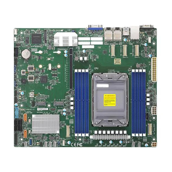
Introduction Congratulations on purchasing your computer motherboard from an industry leader. Supermicro motherboards are designed to provide you with the highest standards in quality and performance. In additon to the motherboard, several important parts that are included in the retail box are listed below. - Page 9 Chapter 1: Introduction Figure 1-1. X12SPO-NTF Motherboard Image Note: All graphics shown in this manual were based upon the latest PCB revision available at the time of publication of the manual. The motherboard you received may or may not look exactly the same as the graphics shown in this manual.
- Page 10 Super X12SPO-NTF/F User's Manual Figure 1-1. X12SPO-F Motherboard Image Note: All graphics shown in this manual were based upon the latest PCB revision available at the time of publication of the manual. The motherboard you received may or may not look exactly the same as the graphics shown in this manual.
- Page 11 JPL1 COM1 USB6/7 (3.0) BAR CODE SAN MAC AST2600 JNCSI1 IPMI_LAN LAN2 LAN1 IPMI CODE MAC CODE USB0/1 BMC_HB_LED MH11 MH12 X12SPO-NTF/-F REV: 2.0 NVMe4/5 NVMe2/3 NVMe0/1 DESIGNED IN USA BIOS LICENSE MH10 MH13 LED_CATERR JTPM1 M.2H_2 M.2-H_1 621A JBT1 USB10 (3.0)
-
Page 12: Quick Reference
NVMe4/5 JNCSI1 IPMI_LAN LAN2 LAN1 IPMI CODE MAC CODE USB0/1 BMC_HB_LED BMC_HB_LED (for -NTF only) COM2 NVMe2/3 MH11 MH12 NVMe0/1 X12SPO-NTF/-F JCPLD1 REV: 2.0 NVMe4/5 NVMe2/3 NVMe0/1 DESIGNED IN USA BIOS LICENSE JPWR1 JNVI2C1 MH10 JVRM1 MH13 DIMMC1 JWD1 LED_CATERR... -
Page 13: Quick Reference Table
Chapter 1: Introduction Quick Reference Table Jumper Description Default Setting JBT1 CMOS Clear Open (Normal) Pins 1-2 (Enabled) JPL1 LAN1/LAN2 Enable Pins 2-3 (Disabled) JPME2 ME Manufacturing Mode Pins 1-2 (Normal) Pins 1-2 (Reset) JWD1 Watch Dog Timer Pins 2-3 (NMI) Description Status BMC_HB_LED... - Page 14 Super X12SPO-NTF/F User's Manual Connector Description NVMe0~9 PCIe 4.0 x8 Slimline SAS Connectors (NVMe4~9 for -NTF only) SLOT6 CPU PCIe 4.0 x16 Slot Onboard Buzzer S-SATA0, S-SATA1 SATA 3.0 Ports with SATA DOM Power S-SGPIO1 Serial Link General Purpose I/O Connection Header Unit Identifier (UID) Switch USB0/1 Back Panel Universal Serial Bus (USB) 2.0 Ports...
-
Page 15: Motherboard Features
Note: Memory speed support depends on the processors used in the system. DIMM Size • Up to 256GB at 1.2V Note: For the latest CPU/memory updates, please refer to our website at http://www.supermicro.com/products/ motherboard. Chipset • Intel C621A Expansion Slots •... - Page 16 Fan status monitoring via IPMI connections • Dual cooling zones System Management • Trusted Platform Module (TPM) 2.0 support • IPMI View, Supermicro IPMI Tool, IPMI CFG • SuperDoctor® 5, Watch Dog, RoHS • Supermicro Server Manager (SSM) LED Indicators •...
- Page 17 IPMI, please visit our website at https://www.super- micro.com/en/solutions/management-software/bmc-resources. Note 4: If you purchase a Supermicro Out of Band (OOB) software license key (Supermicro P/N: SFT-OOB-LIC), please do not change the IPMI MAC address. Once you change the IPMI MAC address, the license is invalid.
- Page 18 Super X12SPO-NTF/F User's Manual Figure 1-3. System Block Diagram ChanB ChanF ChanA VR13 HC ChanE ChanD 7+1 PHASE ChanH 270W ChanC ChanG PECI:30 SOCKET ID:0 IOU3 (IIO PCIe port 4) #0+#1B+#3 PCI-E X16 , Gen4 *10 NVMe (-NTF) 5 * PCI-E X8 , Gen4 , SLIM SAS (10* NVME) *4 NVMe(-F) mini SAS HD*2 10G/1G...
-
Page 19: Processor And Chipset Overview
Chapter 1: Introduction 1.2 Processor and Chipset Overview Built upon the functionality and capability of the 3rd generation Intel Xeon Scalable Processor series, the X12SPO-NTF/F motherboard offers maximum I/O expandability, energy efficiency, and data reliability in a small form factor. If offers a maximum capacity of 256GB, and is optimized for embedded storage solutions, networking applications, or cloud-computing platforms. -
Page 20: System Health Monitoring
Super X12SPO-NTF/F User's Manual 1.4 System Health Monitoring Onboard Voltage Monitors An onboard voltage monitor will scan the voltages of the onboard chipset, memory, CPU, and battery continuously. Once a voltage becomes unstable, a warning is given, or an error message is sent to the screen. -
Page 21: Acpi Features
Windows operating systems. For detailed information regarding OS support, please refer to the Supermicro website. 1.6 Power Supply As with all computer products, a stable power source is necessary for proper and reliable operation. -
Page 22: Serial Port
Super X12SPO-NTF/F User's Manual 1.7 Serial Port The motherboard supports two serial communication connections. COM port 1 and COM header 2 can be used for input/output. The UART provides legacy speeds with a baud rate of up to 115.2 Kbps as well as an advanced speed with baud rates of 250 K, 500 K, or 1 Mb/s to support high-speed serial communication devices. -
Page 23: Chapter 2 Installation
Chapter 2: Installation Chapter 2 Installation 2.1 Static-Sensitive Devices Electrostatic Discharge (ESD) can damage electronic com ponents. To avoid damaging your system board, it is important to handle it very carefully. The following measures are generally sufficient to protect your equipment from ESD. Precautions •... -
Page 24: Processor And Heatsink Installation
Thermal grease is pre-applied on a new heatsink. No additional thermal grease is needed. • Refer to the Supermicro website for updates on processor support. • All graphics in this manual are for illustrations only. Your components may look different. -
Page 25: Overview Of The Processor Carrier Assembly
Chapter 2: Installation Overview of the Processor Carrier Assembly The processor carrier assembly contains the and a processor carrier. 1. Processor 2. Processor Carrier Overview of the CPU Socket The CPU socket is protected by a plastic protective cover. 1. Plastic Protective Cover 2. -
Page 26: Overview Of The Processor Heatsink Module
Super X12SPO-NTF/F User's Manual Overview of the Processor Heatsink Module The Processor Heatsink Module (PHM) contains a heatsink, a processor carrier, and the processor. 1. Heatsink with Thermal Grease 2. Processor Carrier 3. Processor Processor Heatsink Module... -
Page 27: Creating The 3Rd Generation Intel Xeon Scalable Processor Carrier Assembly
CPU Pin 1 Processor Carrier Assembly Note: The following CPU carriers have been successfully tested in our labs and are available from Supermicro. Please order the CPU carriers with the CPU heatsink. SKT-1205L-P4IC-FXC Intel 3rd Generation Xeon Scalable Processors... -
Page 28: Assembling The Processor Heatsink Module
Super X12SPO-NTF/F User's Manual Assembling the Processor Processor Carrier Assembly (Upside Down) Heatsink Module After creating the processor carrier assembly for the processor, mount it onto the heatsink to create the processor heatsink module (PHM): 1. Note the label on top of the heatsink, which marks the heatsink mounting holes as 1, 2, 3, and 4. -
Page 29: Preparing The Cpu Socket For Installation
Chapter 2: Installation Preparing the CPU Socket for Installation This motherboard comes with a plastic protective cover installed on the CPU socket. Remove it from the socket to install the Processor Heatsink Module (PHM). Gently pull up one corner of the plastic protective cover to remove it. CPU Socket with Plastic Protective Cover Remove the plastic protective cover from the CPU socket. -
Page 30: Installing The Processor Heatsink Module
Super X12SPO-NTF/F User's Manual Installing the Processor Heatsink Module After assembling the Processor Heatsink Module (PHM), install it onto the CPU socket: 1. Align hole 1 of the heatsink with the printed triangle on the CPU socket. See the left image below. -
Page 31: Removing The Processor Heatsink Module
Chapter 2: Installation Removing the Processor Heatsink Module Remove the screws in the sequence of 4, 3, 2, 1 Before removing the processor heatsink module (PHM) from the motherboard, shut down the system and then unplug the AC power cord from all power supplies. -
Page 32: Motherboard Installation
JPL1 COM1 USB6/7 (3.0) BAR CODE SAN MAC AST2600 JNCSI1 IPMI_LAN LAN2 LAN1 IPMI CODE MAC CODE USB0/1 BMC_HB_LED MH11 MH12 X12SPO-NTF/-F REV: 2.0 NVMe4/5 NVMe2/3 NVMe0/1 DESIGNED IN USA BIOS LICENSE MH10 MH13 LED_CATERR JTPM1 M.2-H_1 M.2H_2 621A JBT1 USB10 (3.0) -
Page 33: Installing The Motherboard
Chapter 2: Installation Installing the Motherboard 1. Install the I/O shield into the back of the chassis, if applicable. 2. Locate the mounting holes on the motherboard. See the previous page for the location. 3. Locate the matching mounting holes on the chassis. Align the mounting holes on the motherboard against the mounting holes on the chassis. -
Page 34: Memory Support And Installation
Super X12SPO-NTF/F User's Manual 2.4 Memory Support and Installation Note: Check the Supermicro website for recommended memory modules. Important: Exercise extreme care when installing or removing DIMM modules to pre- vent any possible damage. Memory Support The X12SPO-NTF/F supports up to 2048GB of ECC RDIMM/LRDIMM/RDIMM 3DS/ LRDIMM 3DS with speeds of up to 3200MHz in eight slots. -
Page 35: General Guidelines For Optimizing Memory Performance
JPL1 COM1 USB6/7 (3.0) BAR CODE SAN MAC AST2600 JNCSI1 IPMI_LAN LAN2 LAN1 IPMI CODE MAC CODE USB0/1 BMC_HB_LED MH11 MH12 X12SPO-NTF/-F REV: 2.0 NVMe4/5 NVMe2/3 NVMe0/1 DESIGNED IN USA BIOS LICENSE MH10 MH13 LED_CATERR JTPM1 M.2-H_1 M.2H_2 621A JBT1 USB10 (3.0) -
Page 36: Dimm Installation
AST2600 JNCSI1 IPMI_LAN LAN2 LAN1 IPMI CODE MAC CODE USB0/1 BMC_HB_LED into the memory slots based on the MH11 MH12 X12SPO-NTF/-F recommended DIMM population table on REV: 2.0 NVMe4/5 NVMe2/3 NVMe0/1 DESIGNED IN USA BIOS LICENSE MH10 MH13 page 34. -
Page 37: Rear I/O Ports
JPL1 COM1 USB6/7 (3.0) BAR CODE SAN MAC AST2600 JNCSI1 IPMI_LAN LAN2 LAN1 IPMI CODE MAC CODE USB0/1 BMC_HB_LED MH11 MH12 X12SPO-NTF/-F REV: 2.0 NVMe4/5 NVMe2/3 NVMe0/1 DESIGNED IN USA BIOS LICENSE MH10 MH13 LED_CATERR JTPM1 M.2H_2 M.2-H_1 621A JBT1 USB10 (3.0) - Page 38 USB6/7 (3.0) BAR CODE SAN MAC AST2600 JNCSI1 IPMI_LAN LAN2 LAN1 IPMI CODE MAC CODE USB0/1 BMC_HB_LED 2. COM1 MH11 MH12 X12SPO-NTF/-F 3. COM2 REV: 2.0 NVMe4/5 NVMe2/3 NVMe0/1 DESIGNED IN USA BIOS LICENSE MH10 MH13 LED_CATERR JTPM1 M.2-H_1 M.2H_2 621A USB10 (3.0)
- Page 39 LED2 COM1 USB6/7 (3.0) BAR CODE SAN MAC AST2600 JNCSI1 IPMI_LAN LAN2 LAN1 IPMI CODE MAC CODE USB0/1 BMC_HB_LED MH11 MH12 X12SPO-NTF/-F REV: 2.0 NVMe4/5 NVMe2/3 NVMe0/1 DESIGNED IN USA BIOS LICENSE MH10 MH13 LED_CATERR JTPM1 M.2H_2 M.2-H_1 621A JBT1 USB10 (3.0)
- Page 40 SAN MAC AST2600 JNCSI1 IPMI_LAN LAN2 LAN1 IPMI CODE MAC CODE USB0/1 VBUS SSRX- BMC_HB_LED USB_N SSRX+ MH11 MH12 X12SPO-NTF/-F REV: 2.0 NVMe4/5 NVMe2/3 NVMe0/1 USB_P DESIGNED IN USA BIOS LICENSE MH10 Ground SSTX- MH13 LED_CATERR SSTX+ 1. USB0/1 2. USB2/3 JTPM1 M.2H_2...
- Page 41 USB6/7 (3.0) BAR CODE SAN MAC 2. UID LED1 AST2600 JNCSI1 IPMI_LAN LAN2 LAN1 IPMI CODE MAC CODE USB0/1 BMC_HB_LED MH11 MH12 X12SPO-NTF/-F REV: 2.0 NVMe4/5 NVMe2/3 NVMe0/1 DESIGNED IN USA BIOS LICENSE MH10 MH13 LED_CATERR JTPM1 M.2H_2 M.2-H_1 621A JBT1 USB10 (3.0)
-
Page 42: Front Control Panel
JF1 contains header pins for various buttons and indicators that are normally located on a control panel at the front of the chassis. These connectors are designed specifically for use with Supermicro chassis. See the figure below for the descriptions of the front control panel buttons and LED indicators. - Page 43 Chapter 2: Installation Power Button The Power Button connection is located on pins 1 and 2 of JF1. Momentarily contacting both pins will power on/off the system. This button can also be configured to function as a suspend button (with a setting in the BIOS - see Chapter 4).
- Page 44 Super X12SPO-NTF/F User's Manual Power Fail LED The Power Fail LED connection is located on pins 5 and 6 of JF1. Refer to the table below for pin definitions. Power Fail LED Pin Definitions (JF1) Pin# Definition 3.3V PWR Supply Fail Overheat (OH)/Fan Fail Connect an LED cable to pins 7 and 8 of the Front Control Panel to use the Overheat/Fan Fail LED connections.
- Page 45 Chapter 2: Installation NIC1/NIC2 (LAN1/LAN2) The NIC (Network Interface Controller) LED connection for LAN port 1 is located on pins 11 and 12 of JF1, and LAN port 2 is on pins 9 and 10. Attach the NIC LED cables here to display network activity.
- Page 46 Super X12SPO-NTF/F User's Manual Power LED The Power LED connection is located on pins 15 and 16 of JF1. Refer to the table below for pin definitions. Power LED Pin Definitions (JF1) Pins Definition 3.3V Stby PWR LED NMI Button The non-maskable interrupt (NMI) button header is located on pins 19 and 20 of JF1.
-
Page 47: Connectors
LED2 COM1 USB6/7 (3.0) BAR CODE SAN MAC AST2600 JNCSI1 IPMI_LAN LAN2 LAN1 IPMI CODE MAC CODE USB0/1 BMC_HB_LED MH11 MH12 X12SPO-NTF/-F REV: 2.0 NVMe4/5 NVMe2/3 NVMe0/1 DESIGNED IN USA BIOS LICENSE MH10 MH13 LED_CATERR JTPM1 M.2-H_1 M.2H_2 621A JBT1 USB10 (3.0) - Page 48 2. 4-Pin PWR USB6/7 (3.0) BAR CODE SAN MAC AST2600 JNCSI1 IPMI_LAN LAN2 LAN1 IPMI CODE MAC CODE USB0/1 BMC_HB_LED MH11 MH12 X12SPO-NTF/-F REV: 2.0 NVMe4/5 NVMe2/3 NVMe0/1 DESIGNED IN USA BIOS LICENSE MH10 MH13 LED_CATERR JTPM1 M.2-H_1 M.2H_2 621A JBT1 USB10 (3.0)
-
Page 49: Headers
BAR CODE SAN MAC AST2600 JNCSI1 IPMI_LAN LAN2 LAN1 IPMI CODE MAC CODE USB0/1 BMC_HB_LED 3. FAN1 MH11 MH12 X12SPO-NTF/-F 4. FAN2 REV: 2.0 NVMe4/5 NVMe2/3 NVMe0/1 DESIGNED IN USA BIOS LICENSE MH10 5. FAN3 MH13 LED_CATERR 6. FAN4 7. FAN5 JTPM1 M.2H_2... - Page 50 2. JSD2 (DOM PWR) BAR CODE SAN MAC AST2600 JNCSI1 IPMI_LAN LAN2 LAN1 IPMI CODE MAC CODE USB0/1 BMC_HB_LED 3. SGPIO Header MH11 MH12 X12SPO-NTF/-F REV: 2.0 NVMe4/5 NVMe2/3 NVMe0/1 DESIGNED IN USA BIOS LICENSE MH10 MH13 LED_CATERR JTPM1 M.2H_2 M.2-H_1 621A JBT1 USB10 (3.0)
- Page 51 Port 80 connection. Use this header to enhance system performance and data security. Refer to the table below for pin definitions. Please go to the following link for more information on the TPM: http://www.supermicro.com/manuals/other/TPM.pdf. Trusted Platform Module Header Pin Definitions...
- Page 52 2. Power SMB Header USB6/7 (3.0) BAR CODE SAN MAC AST2600 JNCSI1 IPMI_LAN LAN2 LAN1 IPMI CODE MAC CODE USB0/1 BMC_HB_LED MH11 MH12 X12SPO-NTF/-F REV: 2.0 NVMe2/3 NVMe4/5 NVMe0/1 DESIGNED IN USA BIOS LICENSE MH10 MH13 LED_CATERR JTPM1 M.2H_2 M.2-H_1 621A JBT1 USB10 (3.0)
- Page 53 Intrusion Input Ground NVMe I²C Header Connector JNVI²C1 is a management header for the Supermicro AOC NVMe PCIe peripheral cards. Connect the I²C cable to this connector. Note: When installing an NVMe device on the motherboard, connect the first NVMe port (JNVI²C1) first for your system to work properly.
- Page 54 SAN MAC AST2600 JNCSI1 IPMI_LAN LAN2 LAN1 IPMI CODE MAC CODE USB0/1 3. I-SATA2 BMC_HB_LED 4. I-SATA3 MH11 MH12 X12SPO-NTF/-F REV: 2.0 NVMe4/5 NVMe2/3 NVMe0/1 DESIGNED IN USA BIOS LICENSE 5. I-SATA4 MH10 MH13 LED_CATERR 6. I-SATA5 7. I-SATA6 8. I-SATA7 JTPM1 M.2H_2...
- Page 55 Baseboard Management Controller (BMC) and a Network Interface Controller (NIC). For the network sideband interface to work properly, you will need to use a NIC add-on card that supports NC-SI and must use a special cable. Please contact Supermicro at www.supermicro.
- Page 56 2. BMC External I²C Header BAR CODE SAN MAC AST2600 JNCSI1 IPMI_LAN LAN2 LAN1 IPMI CODE MAC CODE USB0/1 BMC_HB_LED MH11 MH12 X12SPO-NTF/-F REV: 2.0 NVMe4/5 NVMe2/3 NVMe0/1 DESIGNED IN USA BIOS LICENSE MH10 MH13 LED_CATERR JTPM1 M.2-H_1 M.2H_2 621A JBT1 USB10 (3.0)
- Page 57 LED2 COM1 USB6/7 (3.0) BAR CODE SAN MAC AST2600 JNCSI1 IPMI_LAN LAN2 LAN1 IPMI CODE MAC CODE USB0/1 BMC_HB_LED MH11 MH12 X12SPO-NTF/-F REV: 2.0 NVMe4/5 NVMe2/3 NVMe0/1 DESIGNED IN USA BIOS LICENSE MH10 MH13 LED_CATERR JTPM1 M.2-H_1 M.2H_2 621A JBT1 USB10 (3.0)
-
Page 58: Jumper Settings
Super X12SPO-NTF/F User's Manual 2.8 Jumper Settings How Jumpers Work To modify the operation of the motherboard, jumpers can be used to choose between optional settings. Jumpers create shorts between two pins to change the function of the connector. Pin 1 is identified with a square solder pad on the printed circuit board. See the diagram below for an example of jumping pins 1 and 2. - Page 59 LED2 COM1 USB6/7 (3.0) BAR CODE SAN MAC AST2600 JNCSI1 IPMI_LAN LAN2 LAN1 IPMI CODE MAC CODE USB0/1 BMC_HB_LED MH11 MH12 X12SPO-NTF/-F REV: 2.0 NVMe4/5 NVMe2/3 NVMe0/1 DESIGNED IN USA BIOS LICENSE MH10 MH13 LED_CATERR JTPM1 M.2-H_1 M.2H_2 621A JBT1 USB10 (3.0)
- Page 60 USB6/7 (3.0) BAR CODE SAN MAC AST2600 JNCSI1 IPMI_LAN 2. Manufacturing Mode LAN2 LAN1 IPMI CODE MAC CODE USB0/1 BMC_HB_LED MH11 MH12 X12SPO-NTF/-F REV: 2.0 NVMe4/5 NVMe2/3 NVMe0/1 DESIGNED IN USA BIOS LICENSE MH10 MH13 LED_CATERR JTPM1 M.2-H_1 M.2H_2 621A USB10 (3.0)
-
Page 61: Led Indicators
USB6/7 (3.0) 2. UID LED BAR CODE SAN MAC AST2600 JNCSI1 IPMI_LAN LAN2 LAN1 IPMI CODE MAC CODE USB0/1 BMC_HB_LED MH11 MH12 X12SPO-NTF/-F REV: 2.0 NVMe4/5 NVMe2/3 NVMe0/1 DESIGNED IN USA BIOS LICENSE MH10 MH13 LED_CATERR JTPM1 M.2H_2 M.2-H_1 621A JBT1 USB10 (3.0) - Page 62 USB6/7 (3.0) 2. BMC Heartbeat LED BAR CODE SAN MAC AST2600 JNCSI1 IPMI_LAN LAN2 LAN1 IPMI CODE MAC CODE USB0/1 BMC_HB_LED MH11 MH12 X12SPO-NTF/-F REV: 2.0 NVMe4/5 NVMe2/3 NVMe0/1 DESIGNED IN USA BIOS LICENSE MH10 MH13 LED_CATERR JTPM1 M.2H_2 M.2-H_1 621A JBT1 USB10 (3.0)
- Page 63 COM1 USB6/7 (3.0) BAR CODE SAN MAC AST2600 JNCSI1 IPMI_LAN LAN2 LAN1 IPMI CODE MAC CODE USB0/1 BMC_HB_LED MH11 MH12 X12SPO-NTF/-F REV: 2.0 NVMe2/3 NVMe4/5 NVMe0/1 DESIGNED IN USA BIOS LICENSE MH10 MH13 LED_CATERR JTPM1 M.2H_2 M.2-H_1 621A USB10 (3.0)
-
Page 64: Chapter 3 Troubleshooting
Chapter 3: Troubleshooting Chapter 3 Troubleshooting 3.1 Troubleshooting Procedures Use the following procedures to troubleshoot your system. If you have followed all of the procedures below and still need assistance, refer to the ‘Technical Support Procedures’ and/ or ‘Returning Merchandise for Service’ section(s) in this chapter. Always disconnect the AC power cord before adding, changing or installing any non hot-swap hardware components. -
Page 65: System Boot Failure
Super X12SPO-NTF/F User's Manual System Boot Failure If the system does not display POST (Power-On-Self-Test) or does not respond after the power is turned on, do the following: 1. Check the screen for an error message. 2. Clear the CMOS settings by unplugging the power cord and contacting both pads on the CMOS clear jumper (JBT1). -
Page 66: When The System Becomes Unstable
Chapter 3: Troubleshooting When the System Becomes Unstable A. If the system becomes unstable during or after OS installation, check the following: 1. CPU/BIOS support: Make sure that your CPU is supported and that you have the latest BIOS installed in your system. 2. - Page 67 Super X12SPO-NTF/F User's Manual 6. To find out if a component is good, swap this component with a new one to see if the system will work properly. If so, then the old component is bad. You can also install the component in question in another system.
-
Page 68: Technical Support Procedures
Before contacting Technical Support, please take the following steps. Also, please note that as a motherboard manufacturer, Supermicro also sells motherboards through its channels, so it is best to first check with your distributor or reseller for troubleshooting services. They should know of any possible problems with the specific system configuration that was sold to you. -
Page 69: Frequently Asked Questions
Updated BIOS files are located on our website at http:// www.supermicro.com/ResourceApps/BIOS_IPMI_Intel.html. Please check our BIOS warning message and the information on how to update your BIOS on our website. Select your motherboard model and download the BIOS file to your computer. Also, check the current BIOS revision to make sure that it is newer than your BIOS before downloading. -
Page 70: Battery Removal And Installation
Chapter 3: Troubleshooting 3.4 Battery Removal and Installation Battery Removal To remove the onboard battery, follow the steps below: 1. Power off your system and unplug your power cable. 2. Locate the onboard battery as shown below. 3. Using a tool such as a pen or a small screwdriver, push the battery lock outwards to unlock it. -
Page 71: Returning Merchandise For Service
For faster service, you can also request a RMA authorization online (http://www.supermicro. com/RmaForm/). This warranty only covers normal consumer use and does not cover damages incurred in shipping or from failure due to the alternation, misuse, abuse or improper maintenance of products. -
Page 72: Chapter 4 Uefi Bios
Chapter 4: BIOS Chapter 4 UEFI BIOS 4.1 Introduction This chapter describes the AMIBIOS™ Setup utility for the motherboard. The BIOS is stored on a chip and can be easily upgraded using a flash program. Note: Due to periodic changes to the BIOS, some settings may have been added or deleted and might not yet be recorded in this manual. -
Page 73: Main Setup
Note: The time is in the 24-hour format. For example, 5:30 P.M. appears as 17:30:00. The date's default value is the BIOS build date after RTC reset. Supermicro X12SPO-NTF BIOS Version This feature displays the version of the BIOS ROM used in the system. - Page 74 Chapter 4: BIOS CPLD Version This feature displays the Complex Programmable Logic Device version. Memory Information Total Memory This feature displays the total size of memory available in the system.
-
Page 75: Advanced
Super X12SPO-NTF/F User's Manual 4.3 Advanced Use the arrow keys to select the Advanced menu and press <Enter> to access the menu features. Warning: Take caution when changing the Advanced settings. An incorrect value, a very high DRAM frequency, or an incorrect DRAM timing setting may make the system unstable. When this occurs, revert to default manufacturer settings. - Page 76 Chapter 4: BIOS Wait For "F1" If Error Use this feature to force the system to wait until the F1 key is pressed if an error occurs. The options are Disabled and Enabled. INT19 (Interrupt 19) Trap Response Interrupt 19 is the software interrupt that handles the boot disk function. When this feature is set to Immediate, the ROM BIOS of the host adapters will "capture"...
- Page 77 Super X12SPO-NTF/F User's Manual CPU Configuration The following CPU information is displayed: • Processor BSP Revision • Processor Socket • Processor ID • Processor Frequency • Processor Max Ratio • Processor Min Ratio • Microcode Revision • L1 Cache RAM (Per Core) •...
- Page 78 Chapter 4: BIOS DCU Streamer Prefetcher (Available when supported by the CPU) Select Enable to enable the DCU (Data Cache Unit) Streamer Prefetcher, which streams and prefetches data and send it to the Level 1 data cache to improve data processing and system performance.
- Page 79 Super X12SPO-NTF/F User's Manual *If the feature above is set to Enabled, the next five features are displayed: Total Memory Encryption Multi-Tenant (TME-MT) Max TME-MT Keys Software Guard Extension (SGX) SGX Factory Reset SW Guard Extensions (SGX) SGX Package Into In-Band Access Limit CPU PA to 46 Bits Use this feature to limit the CPU physical address to 46 bits to support older hyper-v.
- Page 80 Chapter 4: BIOS Intel SST-PP Use this feature to select the base frequency conditions for SST-PP. The options are Base, Config 3, and Config 4. Activate SST-BF Use this feature to enable or disable Intel Speed Select Technology Base Frequency. The options are Disable and Enable.
- Page 81 Super X12SPO-NTF/F User's Manual Hardware PM State Control Hardware P-States This setting allows you to select between OS and hardware-controlled P-states. Select- ing Native Mode allows the OS to choose a P-state. Selecting Out of Band Mode allows the hardware to autonomously choose a P-state without OS guidance. Selecting Native Mode with No Legacy Support functions as Native Mode with no support for older hard- ware.
- Page 82 Chapter 4: BIOS CPU T State Control Software Controlled T-States Use this feature to enable Software Controlled T-States. The options are Disable and Enable. If the feature above is set to Enable, the next feature is available for configuration: T-State Throttle Level Use this feature to enable or disable CPU throttling, which reduces power consumption.
- Page 83 Super X12SPO-NTF/F User's Manual Link L0p Enable Select Enable for the QPI to enter the L0p state for power saving. The options are Dis- able, Enable, and Auto. Link L1 Enable Select Enable for the QPI to enter the L1 state for power saving. The options are Dis- able, Enable, and Auto.
- Page 84 Chapter 4: BIOS PCIe Remote P2P Relaxed Ordering Enable peer-to-peer relaxed ordering to optimize system performance. The options are Disable and Enable. Stale AtoS Use this feature to enable or disable Stale A to S optimization. There are three states in the in-memory directory: invalid (I), snoopAll (A), and shared (S).
- Page 85 Super X12SPO-NTF/F User's Manual 2x Refresh Enable Use this feature to enable 2x memory refresh support to enhance memory performance. The options are Auto, Disable, and Enable. Memory Topology This feature displays the information of memory modules detected by the BIOS. Memory RAS Configuration Setup ...
- Page 86 Chapter 4: BIOS Patrol Scrub Patrol Scrubbing is a process that allows the CPU to correct correctable memory errors detected on a memory module and send the correction to the requestor (the original source). When this item is set to Enable, the IO hub reads and writes back one cache line every 16K cycles if there is no delay caused by internal processing.
- Page 87 Super X12SPO-NTF/F User's Manual PCI-E Port Max Payload Size Selecting Auto for this feature enables the motherboard to automatically detect the maximum Transaction Layer Packet (TLP) size for the connected PCIe device, allowing for maximum I/O efficiency. Selecting 128B or 256B designates maximum packet size of 128 or 256.
- Page 88 Chapter 4: BIOS DMA Control Opt-In Flag Use this feature to enable or disable DMA Control Opt-In Flag. The options are En- able and Disable. Interrupt Remapping Use this feature to enable Interrupt Remapping support, which detects and controls external interrupt requests. The options are Auto, Enable, and Disable. Intel(R) VMD Technology ...
- Page 89 Super X12SPO-NTF/F User's Manual Enable/Disable VMD Use this feature to enable or disable the volume management device for this stack. The options are Disable and Enable. If the feature above is set to Enable, the following features are available for configuration: NVMe0 VMD Use this feature to enable or disable VMD technology for this port.
- Page 90 Chapter 4: BIOS Hot Plug Capable Use this feature to enable or disable hot plug for this port. The options are Dis- able and Enable. VMD Config for IOU 3 Enable/Disable VMD Use this feature to enable or disable the volume management device for this stack. The options are Disable and Enable.
- Page 91 Super X12SPO-NTF/F User's Manual NVME9 VMD Use this feature to enable or disable volume management device for this port. The options are Disable and Enable. Hot Plug Capable Use this feature to enable or disable hot plug for this port. The options are Dis- able and Enable.
- Page 92 Chapter 4: BIOS Port 60/64 Emulation This feature allows legacy I/O support for USB devices like mice and keyboards. The options are Disabled and Enabled. PCIe PLL SSC Use this feature to enable or disable PCIe PLL SSC. The options are Disabled and Enabled. Port 61h Bit-4 Emulation Select Enabled to enable the emulation of Port 61h bit-4 toggling in SMM (System Management Mode).
- Page 93 Super X12SPO-NTF/F User's Manual Support Aggressive Link Power Management When this feature is set to Enable, the SATA AHCI controller manages the power usage of the SATA link. The controller puts the link in a low power mode during extended periods of I/O inactivity, and returns the link to an active state when I/O activity resumes.
- Page 94 Chapter 4: BIOS Support Aggressive Link Power Management When this feature is set to Enable, the SATA AHCI controller manages the power usage of the SATA link. The controller puts the link in a low power mode during extended periods of I/O inactivity, and returns the link to an active state when I/O activity resumes.
- Page 95 Super X12SPO-NTF/F User's Manual IPv4 PXE Support Select Enabled to enable IPv4 PXE boot support. The options are Disabled and Enabled. IPv4 HTTP Support Select Enabled to enable IPv4 HTTP boot support. The options are Disabled and Enabled. IPv6 PXE Support Select Enabled to enable IPv6 PXE boot support.
- Page 96 Chapter 4: BIOS Policy Use this feature to set the policy to automatic or manual. The options or automatic and manual. Save Changes and Exit Select this feature to save the changes for the features above and exit. MAC:xxxxxxxxxxxx-IPv4 Network Configuration MAC:xxxxxxxxxxxx-IPv4 Network Configuration Configured Use this feature to indicate whether the network address is configured successfully.
- Page 97 Super X12SPO-NTF/F User's Manual Client Password Press Enter to create a client username password. KMS TLS Certificate CA Certificate Use this feature to enroll factory defaults or load the CA certificates from a file. The options are Update, Delete, and Export. Client Certificate Use this feature to enroll factory defaults or load the client certificates from a file.
- Page 98 Chapter 4: BIOS MMIO High Granularity Size Use this feature to select the high memory size according to memory-address mapping for the IO hub. The options are 1G, 4G, 16G, 64G, 256G, and 1024G. Maximum Read Request Use this item to select the Maximum Read Request size of the PCIe device, or select Auto to allow the System BIOS to determine the value.
- Page 99 Super X12SPO-NTF/F User's Manual Onboard LAN1 Option ROM Use this feature to select a desired firmware function to be loaded for onboard LAN1. The options are Disabled and Legacy (if the Boot Mode Select feature under the Boot tab is set to Legacy), Disabled and EFI (if the Boot Mode Select feature under the Boot tab is set to UEFI), and Disabled, Legacy, and EFI (if the Boot Mode Select feature under the Boot tab is set to Dual).
- Page 100 Chapter 4: BIOS Device Settings This feature displays the status of a serial port. Change Settings This feature specifies the base I/O port address and the Interrupt Request address of the serial port. Select Auto to allow the BIOS to automatically assign the base I/O and IRQ address.
- Page 101 Super X12SPO-NTF/F User's Manual Parity A parity bit can be sent along with regular data bits to detect data transmission errors. Select Even if the parity bit is set to 0, and the number of 1's in data bits is even. Select Odd if the parity bit is set to 0, and the number of 1's in data bits is odd.
- Page 102 Chapter 4: BIOS SOL/COM2 Console Redirection Select Enabled to use the SOL port for Console Redirection. The options are Disabled and Enabled. *If the feature above is set to Enabled, the following features are available for configuration: Console Redirection Settings Use this feature to specify how the host computer exchanges data with the client computer, which is the remote computer used by the user.
- Page 103 Super X12SPO-NTF/F User's Manual Flow Control Use this feature to set the flow control for Console Redirection to prevent data loss caused by buffer overflow. Send a "Stop" signal to stop sending data when the receiving buffer is full. Send a "Start" signal to start sending data when the receiving buffer is empty. The options are None and Hardware RTS/CTS.
- Page 104 Chapter 4: BIOS *If the feature above is set to Enabled, the following features are available for configuration: EMS Console Redirection Settings This feature allows you to specify how the host computer exchanges data with the client computer, which is the remote computer used by the user. Out-of-Band Mgmt Port The feature selects a serial port in a client server to be used by the Microsoft Windows Emergency Management Services (EMS) to communicate with a remote host server.
- Page 105 Super X12SPO-NTF/F User's Manual UMA-Based Clustering Use this feature to enable or disable Uniform Memory Access (UMA) clustering. The options are Disable (All2All) and Hemishpere (2-clusters). WHEA Support Select Enabled to support the Windows Hardware Error Architecture (WHEA) platform and provide a common infrastructure for the system to handle hardware errors within the Windows OS environment to reduce system crashes and to enhance system recovery and health monitoring.
- Page 106 Use this feature to disable or enable Platform Hierarchy (PH) Randomization. The options are Disabled and Enabled. SMCI BIOS-Based TPM Provision Support Use this feature to enable the Supermicro TPM Provision support. The options are Disabled and Enabled. TXT Support Use this feature to enable or disable TXT Support.
- Page 107 Super X12SPO-NTF/F User's Manual Select IPv4 or IPv6 Use this feature to select which LAN port to boot from. The options are IPv4 and IPv6. Boot Description Highlight the feature and press enter to create a boot description. The description cannot be more than 75 characters.
- Page 108 Chapter 4: BIOS NIC Configuration Link Speed Use this feature to specify the port speed used for the selected boot protocol. The options are Auto Negotiated, 10 Mbps Half, 10 Mbps Full, 100 Mbps Half, and 100 Mbps Full. Wake On LAN Select Enabled for wake on LAN support, which allows the system to wake up when an onboard LAN device receives an incoming signal.
- Page 109 Super X12SPO-NTF/F User's Manual Commit Changes and Exit Use this feature to save all changes and exit TLS settings. Discard Changes and Exit Use this feature to discard all changes and exit TLS settings. Delete Certification Use this feature to delete certification. Intel Virtual RAID on CPU ...
-
Page 110: Event Logs
Chapter 4: BIOS 4.4 Event Logs Use this menu to configure Event Log settings. Change SMBIOS Event Log Settings Enabling/Disabling Options SMBIOS Event Log Change this feature to enable or disable all features of the SMBIOS Event Logging during system boot. The options are Disabled and Enabled. Erasing Settings Erase Event Log If No is selected, data stored in the event log will not be erased. - Page 111 Super X12SPO-NTF/F User's Manual SMBIOS Event Log Standard Settings Log System Boot Event This option toggles the System Boot Event logging to enabled or disabled. The options are Disabled and Enabled. MECI The Multiple Event Count Increment (MECI) counter counts the number of occurrences that a duplicate event must happen before the MECI counter is incremented.
-
Page 112: Ipmi
Chapter 4: BIOS 4.5 IPMI Use this menu to configure Intelligent Platform Management Interface (IPMI) settings. BMC Firmware Revision This feature indicates the IPMI firmware revision used in your system. IPMI STATUS This feature indicates the status of the IPMI firmware installed in your system. System Event Log Enabling/Disabling Options SEL Components... - Page 113 Super X12SPO-NTF/F User's Manual When SEL is Full This feature allows you to decide what the BIOS should do when the system event log is full. Select Erase Immediately to erase all events in the log when the system event log is full. The options are Do Nothing and Erase Immediately.
- Page 114 Chapter 4: BIOS Gateway IP Address This feature displays the Gateway IP address for this computer. The address can be manually entered. This should be in decimal and in dotted quad form (i.e., 172.31.0.1). VLAN This feature displays the virtual LAN settings. The options are Disabled and Enabled. VLAN ID This feature is enabled if VLAN is enabled.
-
Page 115: Security
Super X12SPO-NTF/F User's Manual 4.6 Security Use this menu to configure the following security settings for the system. Administrator Password Press Enter to create a new, or change an existing, Administrator password. Password Check Select Setup for the system to check for a password at Setup. Select Always for the system to check for a password at boot up or upon entering the BIOS Setup utility. - Page 116 Erase - PSID, and Security Erase - Wtihout Password. Password Use this feature to set a password for the Supermicro HDD Security Function. Lockdown Mode Use this feature to put the BIOS into lockdown mode. The options are Enabled and Disabled.
- Page 117 Super X12SPO-NTF/F User's Manual Restore Factory Keys Force System to User Mode. Install factory default Secure Boot key databases. Reset to Setup Mode This feature deletes all Secure Boot key databases from NVRAM. Export Secure Boot variables This feature allows you to copy NVRAM content of Secure boot variables to files in a root folder on a file system device.
- Page 118 Chapter 4: BIOS Append Select Yes to add the KEK from the manufacturer's defaults list to the existing KEK. Select No to load the KEK from a file. Authorized Signatures Update Select Yes to load the DB from the manufacturer's defaults. Select No to load the DB from a file.
- Page 119 Super X12SPO-NTF/F User's Manual OsRecovery Signature Update Select Yes to load the DBR from the manufacturer's defaults. Select No to load the DBR from a file. Append Select Yes to add the DBR from the manufacturer's defaults list to the existing DBR. Select No to load the DBR from a file.
-
Page 120: Boot
Chapter 4: BIOS 4.7 Boot Use this menu to configure Boot settings. Boot Mode Select Use this feature to select the type of device that the system is going to boot from. The options are Legacy, UEFI, and Dual. Legacy to EFI Support Select Enabled to boot EFI OS support after Legacy boot order has failed. - Page 121 Super X12SPO-NTF/F User's Manual • Boot Option #5 • Boot Option #6 • Boot Option #7 • Boot Option #8 Delete Boot Option This feature allows you to select a boot device to delete from the boot priority list. Delete Boot Option Use this feature to remove an EFI boot option from the boot priority list.
-
Page 122: Save & Exit
Chapter 4: BIOS 4.8 Save & Exit Use this menu to save settings and exit from the BIOS. Save Options Discard Changes and Exit Select this option to quit the BIOS Setup without making any permanent changes to the system configuration, and reboot the computer. Select Discard Changes and Exit from the Save &... - Page 123 Super X12SPO-NTF/F User's Manual Default Options Load Optimized Defaults To set this feature, select Restore Defaults from the Save & Exit menu and press <Enter>. These are factory settings designed for maximum system stability, but not for maximum performance. Save As User Defaults To set this feature, select Save as User Defaults from the Save &...
-
Page 124: Appendix A Software
USB/SATA DVD drive, or a USB flash drive, or the IPMI KVM console. 2. Retrieve the proper RST/RSTe driver. Go to the Supermicro web page for your motherboard and click on "Download the Latest Drivers and Utilities", select the proper driver, and copy it to a USB flash drive. - Page 125 Super X12SPO-NTF/F User's Manual 4. During Windows Setup, continue to the dialog where you select the drives on which to install Windows. If the disk you want to use is not listed, click on “Load driver” link at the bottom left corner. Figure A-2.
-
Page 126: Driver Installation
Appendix A: Software A.2 Driver Installation The Supermicro site that contains drivers and utilities for your system is at https://www. supermicro.com/wdl/driver/. Some of these must be installed, such as the chipset driver. After accessing the site, go into the CDR_Images (in the parent directory of the above link) and locate the ISO file for your motherboard. -
Page 127: Superdoctor ® 5
A.3 SuperDoctor ® The Supermicro SuperDoctor 5 is a program that functions in a command-line or web-based interface for Windows and Linux operating systems. The program monitors such system health information as CPU temperature, system voltages, system power consumption, fan speed, and provides alerts via email or Simple Network Management Protocol (SNMP). -
Page 128: Ipmi
There are several BIOS settings that are related to IPMI. Supermicro ships standard products with a unique password for the BMC ADMIN user. This password can be found on a label on the motherboard. For general documentation and information on IPMI, please visit our website at: http://www.supermicro.com/products/nfo/... -
Page 129: Appendix B Standardized Warning Statements
The following statements are industry standard warnings, provided to warn the user of situations which have the potential for bodily injury. Should you have questions or experience difficulty, contact Supermicro's Technical Support department for assistance. Only certified technicians should attempt to install or configure components. - Page 130 Appendix B: Standardized Warning Statements Attention Danger d'explosion si la pile n'est pas remplacée correctement. Ne la remplacer que par une pile de type semblable ou équivalent, recommandée par le fabricant. Jeter les piles usagées conformément aux instructions du fabricant. ¡Advertencia! Existe peligro de explosión si la batería se reemplaza de manera incorrecta.
- Page 131 Super X12SPO-NTF/F User's Manual Product Disposal Warning! Ultimate disposal of this product should be handled according to all national laws and regulations. 製品の廃棄 この製品を廃棄処分する場合、 国の関係する全ての法律 ・ 条例に従い処理する必要があります。 警告 本产品的废弃处理应根据所有国家的法律和规章进行。 警告 本產品的廢棄處理應根據所有國家的法律和規章進行。 Warnung Die Entsorgung dieses Produkts sollte gemäß allen Bestimmungen und Gesetzen des Landes erfolgen.
Need help?
Do you have a question about the X12SPO-NTF/-F and is the answer not in the manual?
Questions and answers