Table of Contents
Advertisement
Available languages
Available languages
Advertisement
Table of Contents

Related Manuals for Supermicro X12SPA-TF


Summary of Contents for Supermicro X12SPA-TF
- Page 1 X12SPA-TF ENGLISH 繁體中文 简体中文 日本語 한국어 QUICK REFERENCE GUIDE Revision 1.0b...
-
Page 3: About Standardized Warning Statements
Should you have questions or experience difficulty, contact Supermicro's Technical Support Department for assistance. Only certified technicians should attempt to install or configure components. Read this section in its entirety before installing or configuring components in the Supermicro chassis. WARNING: This product can expose you to chemicals including lead, known to the State of California to cause cancer and birth defects or other reproductive harm. - Page 4 X12SPA-TF QUICK REFERENCE GUIDE 限用物質含有情況標示聲明書 限 限 用 用 物 物 質 質 含 含 有 有 情 情 況 況 標 標 示 示 聲 聲 明 明 書 書 Declaration of the Presence Condition of the Restricted Substances Marking 設備名稱:主機板...
-
Page 5: Ami Bios Post Codes
X12SPA-TF QUICK REFERENCE GUIDE BIOS POST Codes AMI BIOS POST Codes About AMI BIOS POST Codes The table below lists some of AMI BIOS POST codes for this motherboard. For more information, refer to https://www. supermicro.com/manuals/other/AMI_AptioV_BIOS_POST_Codes_for_SM_Motherboards.pdf. Code Description 0x32 CPU post-memory initialization is started... -
Page 6: Device Installation
X12SPA-TF QUICK REFERENCE GUIDE M.2 Device Installation M.2 Device Installation This motherboard has four M.2 M-key sockets that support M.2 2260/2280/22110 modules. One standoff and a screw are pre-installed into the position of each 2280 mounting hole; one standoff is pre-installed into the position of each 22110 mounting hole. - Page 7 X12SPA-TF QUICK REFERENCE GUIDE M.2 Device Installation 2260 M.2 Device Installation 1. Locate the pre-installed standoff and screw (in the position of 2280 mounting hole). Remove the screw and set it aside. 2. Using a hex socket screwdriver, remove and then re-install the standoff to the position of 2260 mounting hole.
-
Page 8: Memory Population
X12SPA-TF QUICK REFERENCE GUIDE Memory Population Memory Population Note: Unbalanced memory configuration decreases memory performance and is not recommended for Supermicro motherboards. Intel® Optane™ Persistent Memory (PMem) 200 Series Population Table for X12SPA-TF (w/16 Slots) based on the 3rd Generation Intel Xeon Scalable (83xx/63xx/53xx/4314) Series Processors... - Page 9 X12SPA-TF QUICK REFERENCE GUIDE Notes Notes...
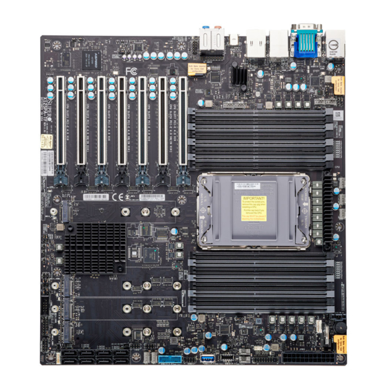
- Page 10 UPERMICR X12SPA-TF . 1.0b uick efeRence uide Motherboard Layout and Features I/O BACK PANEL USB5/6 USB7/8 HD AUDIO USB9/10 (USB3.2 Gen.1) (USB3.2 Gen.1) USB4 LAN2 IPMI_LAN UID-SW LAN1 (USB3.2 Gen.2x2) COM1 UID-LED JPAC1 JSPDIF_OUT AUDIO FP JPWR4 CTRL JPWR3 3242...
-
Page 11: Jumpers And Connectors
• One Supermicro Motherboard • One Quick Reference Guide • Six SATA Cables • One GPU to CPU Power Cable • One I/O Shield • One CPU Carrier Jumpers and Connectors Jumpers Jumper Description Default J9701, J9702 Debug Mode... -
Page 12: Led Indicators
CPU & Memory Support The X12SPA-TF motherboard supports a single 3rd Generation Intel® Xeon® Scalable-SP processor. Memory supports up to 1TB of ECC RDIMM, 4TB of 3DS RDIMM, 2TB of LRDIMM, and 4TB of 3DS LRDIMM with speeds of up to 3200 MHz (2DPC) in 16 DDR4 (288-pin) SMD DIMM slots. -
Page 13: Back Panel I/O Connectors
8. USB8: USB 3.2 Gen. 1 Port 13. Center/LFE Out 18. Mic In 4. COM1 Port 9. LAN2: RJ45 10Gb LAN Port 14. Surround Out 19. UID Switch 5. VGA Port 10. USB5: USB 3.2 Gen. 1 Port 15. S/PDIF Out X12SPA-TF... - Page 14 UPERMICR 美超微電腦股份有限公司 X12SPA-TF 快速參考指南版本 1.0b 主機板元件配置圖 I/O BACK PANEL USB5/6 USB7/8 HD AUDIO USB9/10 (USB3.2 Gen.1) (USB3.2 Gen.1) USB4 LAN2 IPMI_LAN UID-SW LAN1 (USB3.2 Gen.2x2) COM1 UID-LED JPAC1 JSPDIF_OUT AUDIO FP JPWR4 CTRL JPWR3 3242 CTRL JPL1 JPL2 FAN6 FAN D...
- Page 15 單一主機板包裝盒內容清單 • Supermicro 主機板 x1 • 快速參考指南 • SATA 訊號線 x6 • GPU 轉 CPU 電源線 x1 • 後擋板 x1 • CPU 處理器載具 x1 跳線器/連接埠 跳線器 (Jumper) 跳線器 說明 預設值 J9701, J9702 針腳 1-2 (正常) 偵錯模式 JBT1 CMOS 組態資料清除 (內建) 設為短路清除...
- Page 16 線上技術支援及下載 • 聯絡我們 ( 技術支援信箱 ) : www.supermicro.com (Email: support@supermicro.com) • 產品手冊文件: http://www.supermicro.com/support/manuals • 驅動程式及工具程式: https://www.supermicro.com/wdl/driver/ • 產品安全性須知: http://www.supermicro.com/about/policies/safety_information.cfm LED 指示燈 LED 指示燈 LED燈 說明 燈號顏色及狀態 LE3, LE4, LE5, LE6 分別代表 M.2-C04/M.2-C03/M.2-C02/M.2-C01 的 M.2 裝置指示燈 綠燈閃爍:M.2 使用中 LEDBMC BMC 運作指示燈...
- Page 17 備註 • 快速參考指南中的圖例僅供安裝及操作說明使用,可能與實際產品外觀不同。 • 更多跳線器/連接埠/指示燈/記憶體/主機板/中央處理器相關安裝資訊,請參閱 X12SpA-TF 使用手冊》第二章。 《 upermicro 中央處理器與散熱器安裝方式 以針腳1為對齊點 (參考下圖)。再找出 CPU 在已安裝 CPU 的處理器載具上找到塑料安裝卡扣 (下圖標記 a、b、c、d),並將其對齊散熱器上的安裝孔 缺口 (下圖標記 A 及 B),並將其對齊處理 (下圖標記 A、B、C、D)。對應的卡扣及安裝孔對齊後,請小心謹慎地將處理器載具組裝至散熱器上,並 器載具校準點 (下圖標記 a 及 b)。小心地將 確認處理器載具卡扣確實鎖住散熱器。 CPU 的一端插入下圖標記 1 的處理器載具凸 處理器散熱模組 (PHM) 組裝操作說明 榫,再將 CPU 的另一端放入下圖標記 2 的...
- Page 18 UPERMICR 美超微电脑股份有限公司 X12SPA-TF 快速参考指南版本 1.0b 主板元件配置图 I/O后面板 USB5/6 USB7/8 USB9/10 HD AUDIO (USB3.2 Gen.1) (USB3.2 Gen.1) USB4 LAN2 IPMI_LAN UID-SW LAN1 (USB3.2 Gen.2x2) COM1 UID-LED JSPDIF_OUT JPAC1 AUDIO FP JPWR4 CTRL JPWR3 3242 CTRL JPL1 JPL2 FAN6 FAN D FAN C...
- Page 19 包装内容 • Supermicro主板 x1 • 快速参考指南 x1 • SATA数据线 x6 • GPU至CPU电源线 x1 • I/O扩展板 x1 • CPU托架 x1 跳线和接口 跳线 跳线 描述说明 默认 J9701,J9702 诊断模式 针脚1-2(正常) JBT1 清除CMOS(內建) 短接清除CMOS信息 禁用USB11/12 针脚1-2(正常) 禁用USB4 针脚1-2(正常) JPAC1 自动启用/禁用HD 针脚1-2(启用) JPFR1 PFR调试(针脚1-2:PFR CPLD EN_JTAG)...
- Page 20 联系信息 • www.supermicro.com (Email: support@supermicro.com) • 手册:http://www.supermicro.com/support/manuals • 驱动程序和实用程序:https://www.supermicro.com/wdl/driver/ • 安全:http://www.supermicro.com/about/policies/safety_information.cfm LED 指示器 LED 指示器 描述说明 颜色/状态 LE3,LE4,LE5,LE6 用于M.2-C04/M.2-C03/M.2-C02/M.2-C01的M.2 LED 绿灯闪烁:设备工作中 LEDBMC BMC心跳LED 绿灯闪烁:BMC 正常 LEDPWR 板载电源LED 绿灯常亮:开机 UID-LED 单元标识符(UID) LED 蓝灯常亮:设备已识别 CPU和内存支持 X12SPA-TF主板支持单个第3代Intel®Xeon® Scalable-SP(可扩展SP)处理器。内存支持高达1TB的ECC RDIMM、4TB的3DS RDIMM、2TB的LRDIMM以及4TB的3DS LRDIMM,在16个DDR4(288针)SMD DIMM插 槽中的速度高达3200 MHz(2DPC)。在这些DIMM插槽中填充一对相同类型和大小的内存模块将产生交错内存,这...
- Page 21 12. USB4:USB 3.2 Gen. 2x2端口 17. 线路输出 3. USB10:USB 2.0端口 8. USB8:USB 3.2 Gen. 1端口 13. 中心/LFE输出 18. 麦克风输入 4. COM1端口 9. LAN2:RJ45 10Gb LAN端口 14. 环绕输出 19. UID开关 5. VGA 端口 10. USB5:USB 3.2 Gen. 1端口 15. S/PDIF输出 X12SPA-TF...
- Page 22 UPERMICR X12SPA-TF クイック参照ガイド 1.0b 版 マザーボードのレイアウトと機能 I/O バックパネル USB5/6 USB7/8 HD AUDIO USB9/10 (USB3.2 Gen.1) (USB3.2 Gen.1) USB4 LAN2 IPMI_LAN UID-SW LAN1 (USB3.2 Gen.2x2) COM1 UID-LED JPAC1 JSPDIF_OUT AUDIO FP JPWR4 CTRL JPWR3 3242 CTRL JPL1 JPL2 FAN6 FAN D...
- Page 23 パッケージ内容 • Supermicro マザーボード 1枚 • クイック参照ガイド 1個 • SATA ケーブル 6本 • GPU - CPU 電源ケーブル 1本 • I/O シールド 1個 • CPU キャリアボード 1個 ジャンパーおよびコネクタ ジャンパー ジャンパー 説明 デフォルト J9701、J9702 デバッグモード ピン 1-2 (ノーマル) JBT1 CMOSクリア (基板上) CMOSクリア用の短いパッド...
- Page 24 UID-LED 装置識別子(UID)LED ブルー オン:装置を識別済み CPU およびメモリサポート X12SPA-TF マザーボードは、単一の第3世代 Intel® Xeon® Scalable-SP プロセッサに対応しています。メモリは最大 1TB のECC RDIMM、4TB の 3DS RDIMM、2TB の LRDIMM、および 4TB の 3DS LRDIMMに対応しており、16個のDDR4(288ピン)SMD DIMM スロットで最大 3200MHz(2DPC)の速度を実現します。これらの DIMM スロットにタイプとサイズが同じメモリモジュールのペアを装着した場合、インターリーブメモリが生 成されてメモリパフォーマンスが向上します。メモリを取り付ける際には、1DPC および 2DPC を推奨します。一部の第3世代のみ。Intel Xeon Scalable- SP プロセッサは Intel Optane Persistent Memory(PMem)200 シリーズに対応しています。...
- Page 25 3. USB10:USB 2.0 ポート 8. USB8:USB 3.2 Gen. 1 ポート 13. センター/ LFE 出力 18. マイク入力 4. COM1 ポート 9. LAN2:RJ45 10Gb LAN ポート 14. サラウンド出力 19. UID スイッチ 5. VGA ポート 10. USB5:USB 3.2 Gen. 1 ポート 15. S/PDIF 出力 X12SPA-TF...
- Page 26 UPERMICR X12SPA-TF 간편 참조 가이드 개정판 1.0b 메인보드 레이아웃 및 특징 I/O BACK PANEL USB7/8 USB5/6 USB9/10 HD AUDIO (USB3.2 Gen.1) (USB3.2 Gen.1) USB4 LAN2 IPMI_LAN UID-SW LAN1 (USB3.2 Gen.2x2) COM1 UID-LED JPAC1 JSPDIF_OUT AUDIO FP JPWR4 CTRL JPWR3 3242...
- Page 27 내용물 • Supermicro 메인보드 1개 • 간편 참조 가이드 1부 • SATA 케이블 6개 • GPU와 CPU 연결 전원 케이블 1개 • I/O 쉴드 1개 • CPU 캐리어 1개 점퍼 및 커넥터 점퍼 점퍼 설명 기본값 J9701, J9702 디버그 모드...
- Page 28 인터리브 메모리가 발생하여 메모리 성능이 향상됩니다. 메모리 설치 시 1DPC 및 2DPC가 권장됩니다. 특정 3세대 Intel Xeon Scalable-SP 프로세서만 Intel Optane Persistent Memory(PMem) 200 시리즈를 지원합니다. 참고: 1) 메모리 최적화를 위해 반드시 Supermicro의 인증을 받은 DIMM 모듈을 사용해야 합니다. 최신 메모리 업 데이트는 웹사이트(http://www.supermicro.com/products/motherboard)를 참조하십시오.
- Page 29 8. USB8: USB 3.2 Gen. 1 포트 13. 중앙/LFE 출력 18. 마이크 입력 4. COM1 포트 9. LAN2: RJ45 10Gb LAN 포트 14. 서라운드 출력 19. UID 스위치 5. VGA 포트 10. USB5: USB 3.2 Gen. 1 포트 15. S/PDIF 출력 X12SPA-TF...
- Page 30 X12SPA-TF QUICK REFERENCE GUIDE Notes Notes...
Need help?
Do you have a question about the X12SPA-TF and is the answer not in the manual?
Questions and answers