
Related Manuals for Supermicro X12SDV-10CR-SP6F


Summary of Contents for Supermicro X12SDV-10CR-SP6F
- Page 1 X12SDV-4C/8C/10C-SP6F X12SDV-8CE-SP4F X12SDV-10CR-SP6F USER'S MANUAL Revision 1.0a...
- Page 2 State of California, USA. The State of California, County of Santa Clara shall be the exclusive venue for the resolution of any such disputes. Supermicro's total liability for all claims will not exceed the price paid for the hardware product.
- Page 3 B-Key, one E-Key). The Supermicro X12SDV-4C/8C/10C-SP6F and X12SDV-10CR-SP6F series motherboards feature six LAN ports including two 25 GbE ports and four GbE ports. The Supermicro X12SDV-8CE-SP4F motherboard is designed to support extended working temperatures with two 25 GbE ports and two GbE ports. These motherboards also feature onboard Trusted Platform Module (TPM) 2.0 headers for hardware-based security function...
- Page 4 X12SDV-4C/8C/10C-SP6F, X12SDV-8CE-SP4F and X12SDV-10CR-SP6F User's Manual Contacting Supermicro Headquarters Address: Super Micro Computer, Inc. 980 Rock Ave. San Jose, CA 95131 U.S.A. Tel: +1 (408) 503-8000 Fax: +1 (408) 503-8008 Email: marketing@supermicro.com (General Information) Sales-USA@supermicro.com (Sales Inquiries) Government_Sales-USA@supermicro.com (Gov. Sales Inquiries) support@supermicro.com (Technical Support)
-
Page 5: Table Of Contents
Preface Table of Contents Chapter 1 Introduction 1.1 Checklist ..........................8 Quick Reference .......................12 Quick Reference Table ......................14 Motherboard Features .......................16 1.2 Processor and Chipset Overview ..................19 1.3 Special Features ........................19 Recovery from AC Power Loss ..................19 1.4 System Health Monitoring ....................20 Onboard Voltage Monitors ....................20 Fan Status Monitor with Firmware Control ...............20 Environmental Temperature Control .................20... - Page 6 X12SDV-4C/8C/10C-SP6F, X12SDV-8CE-SP4F and X12SDV-10CR-SP6F User's Manual 2.6 Connectors .........................37 Power Connections ......................37 Headers ..........................39 2.7 Jumper Settings .........................50 How Jumpers Work ......................50 2.8 LED Indicators ........................56 Chapter 3 Troubleshooting 3.1 Troubleshooting Procedures ....................59 Before Power On ......................59 No Power ..........................59 No Video ...........................60...
- Page 7 Preface Appendix D UEFI BIOS Recovery...
-
Page 8: Checklist
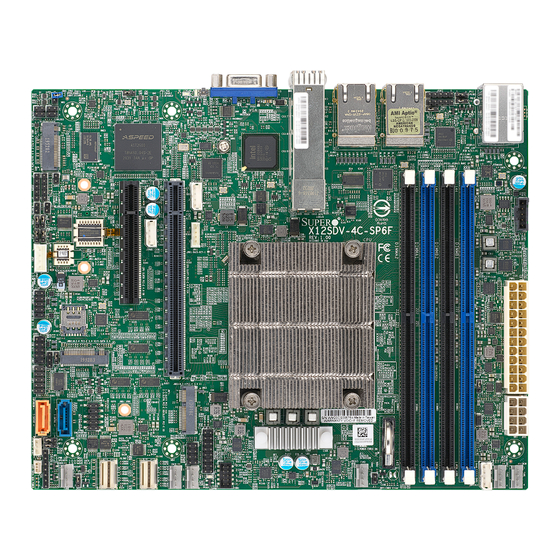
Introduction Congratulations on purchasing your computer motherboard from an industry leader. Supermicro motherboards are designed to provide you with the highest standards in quality and performance. In addition to the motherboard, several important parts that are included in the retail box are listed below. - Page 9 Chapter 1: Introduction Figure 1-1. X12SDV-4C/8C/10C-SP6F Motherboard Image Note: All graphics shown in this manual were based upon the latest PCB revision available at the time of publication of the manual. The motherboard you received may or may not look exactly the same as the graphics shown in this manual.
- Page 10 X12SDV-4C/8C/10C-SP6F, X12SDV-8CE-SP4F and X12SDV-10CR-SP6F User's Manual Figure 1-1. X12SDV-8CE-SP4F Motherboard Image Note: All graphics shown in this manual were based upon the latest PCB revision available at the time of publication of the manual. The motherboard you received may or may not look exactly the same as the graphics shown in this manual.
- Page 11 Chapter 1: Introduction Figure 1-2. X12SDV-4C/8C/10C-SP6F, X12SDV-8CE-SP4F, X12SDV-10CR-SP6F Motherboard Layout (not drawn to scale) JPL1 JBM1 JPG1 JSDP2 JSDP3 JPL2 JLANLED3 AST2600 Intel IPMI_LAN JLAN2 JLAN1 i350-AM2 USB4/5 (3.0) JMD1_SRW1 LAN3/4 LAN1/2 LEDM1 JOPPS LEDT4 LEDT3 JMD2_SRW1 JPI2C1 JNVI2C1 LEDT1...
-
Page 12: Quick Reference
X12SDV-4C/8C/10C-SP6F, X12SDV-8CE-SP4F and X12SDV-10CR-SP6F User's Manual Quick Reference JPL2 LAN5/6 IPMI LAN SLOT7 LEDM1 JSDP2 JMD1_SRW1 LAN3/4 USB4/5 JSDP3 LED3 SLOT6 LAN1/2 JBM1 JPL1 LED2 JPG1 JUIDB1 JPL1 JBM1 JPG1 JSFPLED1 JSDP2 JSDP3 JPL2 JLANLED3 JLANLED3 JMD1 AST2600 Intel JMD2_SRW1... - Page 13 Chapter 1: Introduction Figure 1-3. Motherboard Model Variation Table X12SDV-4C/8C/10C-SP6F, X12SDV-8CE-SP4F and X12SDV-10CR-SP6F Variations Motherboard X12SDV-4C- X12SDV-8C- X12SDV-8CE- X12SDV-10C- X12SDV-10CR- Model SP6F SP6F SP4F SP6F SP6F Processor Name D-1718T D-1736NT D-1732TE D-1747NTE D-1844NT Number of Cores Cache 10 MB 15 MB...
-
Page 14: Quick Reference Table
X12SDV-4C/8C/10C-SP6F, X12SDV-8CE-SP4F and X12SDV-10CR-SP6F User's Manual Quick Reference Table Jumper Description Default Setting SIM Card Detection Pins 1-2 (High Active) JBM1 IPMI Shared LAN Enable/Disable Open (Enabled) JBT1 CMOS Clear Open (Normal) JNS1 SlimSAS Interface Selection Pins 2-3 (PCIe x4) - Page 15 Chapter 1: Introduction Connector Description JMD1_SRW1, JMD2_SRW1, M.2 Mounting Holes JM2_SRW2, JMD3_SRW1 JNVI2C1 Non-Volatile Memory (NVMe) I2C Header JOPPS Reserved for One Pulse Per Second JPH1 4-pin HDD Power Connector JPI2C1 Power System Management (SMB) I2C Header JPWR1 24-pin ATX Power Connector 8-pin 12 V DC Power Connector for CPU (Required) or alternate single power input for JPV1 when the 24-pin ATX power is not in use...
-
Page 16: Motherboard Features
DIMM Size • 8, 16, 32, 64 GB. Note: For the latest CPU/memory updates, refer to our website at http://www.supermicro.com/products/motherboard. Expansion Slots • One PCIe 4.0 x16 Slot (x16 SLOT7) or two PCIe 4.0 x8 Slots (x8 SLOT6, x8 SLOT7) •... - Page 17 Chapter 1: Introduction Motherboard Features Peripheral Devices • Two USB 3.0 ports on the rear I/O panel (USB4/5) • Two front accessible USB 2.0 headers with two USB connections (USB0/1, USB2/3) BIOS • 256 Mb AMI BIOS SPI Flash BIOS ®...
- Page 18 X12SDV-4C/8C/10C-SP6F, X12SDV-8CE-SP4F and X12SDV-10CR-SP6F User's Manual Figure 1-4. System Block Diagram DDR4 2400/2667/2933 MHz PCIe 4.0 x16 PCIe Switch JPCIe1 SLOT7 PCIe 4.0 x16 PE1[15:0] JLAN1 JPCIe2 SLOT6 PCIe 4.0 x8 25G PHY PCIe 3.0 x1 I210IT Flexible I/O SFP28 PCIe 3.0 x1...
-
Page 19: Processor And Chipset Overview
Built upon the functionality and capability of the Intel Xeon D-1700 series and Intel Xeon D-1800 series processors, the X12SDV-4C/8C/10C-SP6F, X12SDV-8CE-SP4F, and X12SDV-10CR-SP6F motherboards provide system performance, power efficiency, and feature sets to address the needs of next-generation computer users. -
Page 20: System Health Monitoring
X12SDV-4C/8C/10C-SP6F, X12SDV-8CE-SP4F and X12SDV-10CR-SP6F User's Manual 1.4 System Health Monitoring Onboard Voltage Monitors The onboard voltage monitor will continuously scan crucial voltage levels. Once a voltage becomes unstable, a warning is given, or an error message is sent to the screen. You can adjust the voltage thresholds to define the sensitivity of the voltage monitor. -
Page 21: Acpi Features
It is even more important for processors that have high CPU clock rates where noisy power transmission is present. The X12SDV-4C/8C/10C-SP6F, X12SDV-8CE-SP4F, and X12SDV-10CR-SP6F motherboards accommodate a 24-pin ATX power supply. Although most power supplies generally meet the specifications required by the CPU, some are inadequate. The 8-pin connector is for 12 V DC input. -
Page 22: Chapter 2 Installation
X12SDV-4C/8C/10C-SP6F, X12SDV-8CE-SP4F and X12SDV-10CR-SP6F User's Manual Chapter 2 Installation 2.1 Static-Sensitive Devices Electrostatic Discharge (ESD) can damage electronic com ponents. To avoid damaging your system board, it is important to handle it very carefully. The following measures are generally sufficient to protect your equipment from ESD. -
Page 23: Motherboard Installation
Chapter 2: Installation 2.2 Motherboard Installation All motherboards have standard mounting holes to fit different types of chassis. Make sure that the locations of all the mounting holes for both the motherboard and the chassis match. Although a chassis may have both plastic and metal mounting fasteners, metal ones are highly recommended because they ground the motherboard to the chassis. -
Page 24: Installing The Motherboard
X12SDV-4C/8C/10C-SP6F, X12SDV-8CE-SP4F and X12SDV-10CR-SP6F User's Manual Installing the Motherboard 1. Install the I/O shield into the back of the chassis, if applicable. 2. Locate the mounting holes on the motherboard. See the previous page for the location. 3. Locate the matching mounting holes on the chassis. Align the mounting holes on the motherboard against the mounting holes on the chassis. -
Page 25: Memory Support And Installation
Chapter 2: Installation 2.3 Memory Support and Installation Note: Check the Supermicro website for recommended memory modules. Important: Exercise extreme care when installing or removing DIMM modules to pre- vent any possible damage. Memory Support The X12SDV-4C/8C/10C-SP6F, X12SDV-8CE-SP4F and X12SDV-10CR-SP6F motherboards support up to 256 GB of ECC and Non-ECC RDIMM/UDIMM DDR4 memory with speeds of up to 2933 MT/s in four memory slots. -
Page 26: General Guidelines For Optimizing Memory Performance
X12SDV-4C/8C/10C-SP6F, X12SDV-8CE-SP4F and X12SDV-10CR-SP6F User's Manual General Guidelines for Optimizing Memory Performance • It is recommended to use DDR4 memory of the same type, size, and speed. • Mixed DIMM speeds can be installed. However, all DIMMs will run at the speed of the slowest DIMM. -
Page 27: Dimm Installation
Chapter 2: Installation DIMM Installation JPL1 JBM1 JPG1 JSDP2 JSDP3 JPL2 JLANLED3 1. Insert DIMM modules in the following AST2600 Intel IPMI_LAN JLAN2 JLAN1 i350-AM2 USB4/5 (3.0) JMD1_SRW1 LAN3/4 LAN1/2 LEDM1 order: DIMMA1, DIMMB1, then DIMMA2, JOPPS LEDT4 LEDT3 JMD2_SRW1 JPI2C1 JNVI2C1 LEDT1... -
Page 28: Rear I/O Ports
X12SDV-4C/8C/10C-SP6F, X12SDV-8CE-SP4F and X12SDV-10CR-SP6F User's Manual 2.4 Rear I/O Ports See Figure 2-1 below for the locations and descriptions of the various I/O ports on the rear of the motherboard. JPL1 JBM1 JPG1 JSDP2 JSDP3 JPL2 JLANLED3 AST2600 Intel IPMI_LAN... - Page 29 Chapter 2: Installation VGA Port A video (VGA) port is located on the rear I/O panel. Refer to the board layout below for the location. LAN Ports Four Gigabit Ethernet RJ45 ports (LAN1/2/3/4) and two SFP28 25 G LAN ports (LAN5/6) are located on the rear I/O panel.
- Page 30 X12SDV-4C/8C/10C-SP6F, X12SDV-8CE-SP4F and X12SDV-10CR-SP6F User's Manual Universal Serial Bus (USB) Ports There are two USB 3.0 ports (USB4/5) on the rear I/O panel and two USB 2.0 headers (USB0/1 and USB2/3) on the motherboard. The onboard headers can be used to provide front side USB access with a cable (not included).
- Page 31 Note: UID can also be triggered via IPMI on the motherboard. For more information on IPMI, refer to the IPMI User's Guide posted on our website at https://www.supermicro. com/support/manuals/. UID Switch...
-
Page 32: Front Control Panel
JF1 contains header pins for various buttons and indicators that are normally located on a control panel at the front of the chassis. These connectors are designed specifically for use with Supermicro chassis. See the figure below for the descriptions of the front control panel buttons and LED indicators. - Page 33 Chapter 2: Installation Power Button The Power Button connection is located on pins 1 and 2 of JF1. Momentarily contacting both pins will power on/off the system. This button can also be configured to function as a suspend button (with a setting in the BIOS – see Chapter 4). To turn off the power when the system is in suspend mode, press the button for 4 seconds or longer.
- Page 34 X12SDV-4C/8C/10C-SP6F, X12SDV-8CE-SP4F and X12SDV-10CR-SP6F User's Manual Overheat (OH)/Fan Fail/PWR Fail LED Connect an LED cable to pins 7 and 8 to use the Overheat (OH)/Fan Fail/PWR Fail LED connections. The LED on pin 8 provides warnings of overheat, fan failure, or power failure.
- Page 35 Chapter 2: Installation HDD LED The HDD LED connection is located on pins 13 and 14 of JF1. Attach a cable to pin 14 to show hard drive activity status. Refer to the table below for pin definitions. HDD LED Pin Definitions (JF1) Pins Definition...
- Page 36 X12SDV-4C/8C/10C-SP6F, X12SDV-8CE-SP4F and X12SDV-10CR-SP6F User's Manual Power Fail LED Connect an LED cable to Power Fail connections on pins 5 and 6 of JF1 to provide warnings for a power failure. Refer to the table below for pin definitions. PWR Fail LED...
-
Page 37: Connectors
Chapter 2: Installation 2.6 Connectors Power Connections ATX Power Supply Connector The 24-pin power supply connector (JPWR1) meets the ATX SSI EPS 24-pin specification. The 8-pin (JPV1) connector is used to provide alternative power for a special enclosure when the 24-pin ATX power is not in use. ATX Power 24-pin Connector Pin Definitions Pin#... - Page 38 X12SDV-4C/8C/10C-SP6F, X12SDV-8CE-SP4F and X12SDV-10CR-SP6F User's Manual 8-Pin Power Connector The 8-pin (JPV1) connector is used to provide alternative power for a special enclosure when the 24-pin ATX power is not in use. Refer to the table below for pin definitions.
-
Page 39: Headers
Chapter 2: Installation Headers JMD3 M.2-H PCIe 3.0 X1 Chassis Intrusion A Chassis Intrusion header is located at JL1 on the motherboard. Attach the appropriate cable from the chassis to inform you of a chassis intrusion when the chassis is opened. Refer to 3_SRW1 the table below for pin definitions. - Page 40 X12SDV-4C/8C/10C-SP6F, X12SDV-8CE-SP4F and X12SDV-10CR-SP6F User's Manual Disk-On-Module Power Connector One power connector for SATA Disk-On-Module (DOM) devices is located at JSD1. Connect appropriate cables here to provide power support for your Serial Link DOM devices. DOM Power Pin Definitions Pin#...
- Page 41 Chapter 2: Installation Fan Headers There are six 4-pin fan headers (FAN1 – FAN4, FANA, FANB) on the motherboard. All these 4-pin fan headers are backwards compatible with traditional 3-pin fans. However, fan speed control is available for 4-pin fans only by Thermal Management via the Hardware Monitoring in the BIOS.
- Page 42 I-SATA 3.0 Ports This motherboard has two I-SATA 3.0 ports (I-SATA1, I-SATA3). I-SATA1 can be used with Supermicro SuperDOMs that are yellow SATA DOM connectors with power pins built in, and do not require external power cables. Supermicro SuperDOMs are backwards compatible with regular SATA HDDs or SATA DOMs that need external power cables.
- Page 43 Chapter 2: Installation JOPPS JOPPS is reserved for One Pulse Per Second. JSDP1 – JSDP4 JSDP1, JSDP2, JSDP3, and JSDP4 are reserved for time synchronization. 1. JOPPS JPL1 JBM1 JPG1 JSDP2 JSDP3 2. JSDP1 JPL2 JLANLED3 AST2600 Intel 3. JSDP2 IPMI_LAN JLAN2 JLAN1...
- Page 44 X12SDV-4C/8C/10C-SP6F, X12SDV-8CE-SP4F and X12SDV-10CR-SP6F User's Manual LAN5/6 Activity LED JSFPLED1 is the activity LED header for LAN5/6. LAN Activity LED JLANLED1 is the activity LED header for LAN1, JLANLED2 is the activity LED header for LAN2, and JLANLED3 is the activity LED header for LAN3/4.
- Page 45 Chapter 2: Installation M.2 Slot This motherboard has three M.2 slots (JMD1, JMD2, JMD3) . M.2 was formerly known as Next Generation Form Factor (NGFF) and serves to replace mini PCIe. M.2 allows for a variety of card sizes, increased functionality, and spatial efficiency. JMD1 supports an M-Key PCIe 3.0 x4 or SATA 3.0 device in the 2280 form factor.
- Page 46 Clock Data Power Fail Ground NVMe I C Header The connector at JNVI2C1 is a management header for the Supermicro AOC NVMe PCIe peripheral cards. Connect the I C cable to these connectors. 1. Power SMB I C Header JPL1...
- Page 47 Chapter 2: Installation SGPIO Header There is one Serial Link General Purpose Input/Output (I-SGPIO1) header located on the motherboard. Refer to the table below for pin definitions. SGPIO Header Pin Definitions Pin# Definition Pin# Definition Ground SSATA Data SSATA Load Ground SSATA Clock SlimSAS Connectors...
- Page 48 X12SDV-4C/8C/10C-SP6F, X12SDV-8CE-SP4F and X12SDV-10CR-SP6F User's Manual Speaker/Power LED Pins 1-3 of JD1 are used for power LED indication, and pins 4-7 are for the speaker. Note that the speaker connector pins are used with an external speaker. Refer to the tables below for pin definitions.
- Page 49 Port 80 connection. Use this header to enhance system performance and data security. Refer to the table below for pin definitions. Go to the following link for more information on the TPM: http://www.supermicro.com/manuals/other/TPM.pdf. Trusted Platform Module Header Pin Definitions...
-
Page 50: Jumper Settings
X12SDV-4C/8C/10C-SP6F, X12SDV-8CE-SP4F and X12SDV-10CR-SP6F User's Manual 2.7 Jumper Settings How Jumpers Work To modify the operation of the motherboard, jumpers can be used to choose between optional settings. Jumpers create shorts between two pins to change the function of the connector. - Page 51 Chapter 2: Installation Watchdog Timer Watchdog (JWD1) is a system monitor that can reboot the system when a software application hangs. Close pins 1-2 to reset the system if an application hangs. Close pins 2-3 to generate a non-maskable interrupt (NMI) signal for the application that hangs. Refer to the table below for jumper settings.
- Page 52 X12SDV-4C/8C/10C-SP6F, X12SDV-8CE-SP4F and X12SDV-10CR-SP6F User's Manual SlimSAS Interface Selection Use the JNS1 jumper to set the SlimSAS port to either function as four SATA ports or a single PCIe x4 NVMe interface. The default settings is PCIe x4. SlimSAS Interface Selection...
- Page 53 Chapter 2: Installation LAN1, LAN2, LAN3/4 Enable/Disable Use JPL1 to enable or disable LAN1, JPL2 to enable or disable LAN2, and JPL3 to enable or disable LAN3/4. The default setting is Enabled. LAN Port Enable/Disable Jumper Settings Jumper Setting Definition Pins 1-2 Enabled (Default) Pins 2-3...
- Page 54 X12SDV-4C/8C/10C-SP6F, X12SDV-8CE-SP4F and X12SDV-10CR-SP6F User's Manual IPMI Shared LAN Enable/Disable Set the JBM1 jumper to enable or disable IPMI shared access on LAN1 (Intel I210-AT). The default settings is Enabled. IPMI Share LAN Enable/Disable Jumper Settings Jumper Setting Definition Pins 1-2 (Open)
- Page 55 Chapter 2: Installation Force Power On JPF1 is the Force Power On jumper. The default settings is ATX Mode. Force Power On Jumper Settings Jumper Setting Definition Pins 1-2 ATX (Default) Pins 2-3 Force PS-ON Mode 1. Force Power On JPL1 JBM1 JPG1...
-
Page 56: Led Indicators
X12SDV-4C/8C/10C-SP6F, X12SDV-8CE-SP4F and X12SDV-10CR-SP6F User's Manual 2.8 LED Indicators Power LED LED1 is the Power LED. When this LED is lit, power is present on the motherboard. In suspend mode, this LED will blink on and off. Turn off the system and unplug the power cord before removing or installing components. - Page 57 Chapter 2: Installation BMC Heartbeat LED LEDM1 is the BMC heartbeat LED. When the LED is blinking green, BMC is functioning normally. Refer to the table below for the LED status. BMC Heartbeat LED Indicator LED Color Definition Green: Blinking BMC Normal LAN LEDs Four LAN ports (LAN1 –...
- Page 58 X12SDV-4C/8C/10C-SP6F, X12SDV-8CE-SP4F and X12SDV-10CR-SP6F User's Manual SFP LAN LEDs SFP28 25 G/10 G LAN LED indicators are located on the rear I/O panel. Refer to the tables below for more information. LAN Activity LED (Left) LAN Link LED (Right) LED State...
-
Page 59: Chapter 3 Troubleshooting
Chapter 3: Troubleshooting Chapter 3 Troubleshooting 3.1 Troubleshooting Procedures Use the following procedures to troubleshoot your system. If you have followed all of the procedures below and still need assistance, refer to the ‘Technical Support Procedures’ and/ or ‘Returning Merchandise for Service’ section(s) in this chapter. Always disconnect the AC power cord before adding, changing or installing any non hot-swap hardware components. -
Page 60: No Video
X12SDV-4C/8C/10C-SP6F, X12SDV-8CE-SP4F and X12SDV-10CR-SP6F User's Manual No Video 1. If the power is on, but you have no video, remove all add-on cards and cables. 2. Use the speaker to determine if any beep codes are present. Refer to Appendix A for details on beep codes. -
Page 61: Losing The System's Setup Configuration
Chapter 3: Troubleshooting Losing the System's Setup Configuration 1. Make sure that you are using a high-quality power supply. A poor-quality power supply may cause the system to lose the CMOS setup information. Refer to Chapter 2 for details on recommended power supplies. 2. - Page 62 X12SDV-4C/8C/10C-SP6F, X12SDV-8CE-SP4F and X12SDV-10CR-SP6F User's Manual 3. Use the minimum configuration for troubleshooting: Remove all unnecessary components (starting with add-on cards first), and use the minimum configuration (but with the CPU and a memory module installed) to identify the trouble areas. Refer to the steps listed in Section A above for proper troubleshooting procedures.
-
Page 63: Technical Support Procedures
Before contacting Technical Support, take the following steps. Also, note that as a motherboard manufacturer, Supermicro also sells motherboards through its channels, so it is best to first check with your distributor or reseller for troubleshooting services. They should know of any possible problems with the specific system configuration that was sold to you. -
Page 64: Frequently Asked Questions
Note: The SPI BIOS chip used on this motherboard cannot be removed. Send your motherboard back to our RMA Department at Supermicro for repair. For BIOS Recov- ery instructions, refer to the AMI BIOS Recovery Instructions posted at http://www. -
Page 65: Battery Removal And Installation
Chapter 3: Troubleshooting 3.4 Battery Removal and Installation Battery Removal To remove the onboard battery, follow the steps below: 1. Power off your system and unplug your power cable. 2. Locate the onboard battery as shown below. 3. Using a tool such as a pen or a small screwdriver, push the battery lock outwards to unlock it. -
Page 66: Returning Merchandise For Service
X12SDV-4C/8C/10C-SP6F, X12SDV-8CE-SP4F and X12SDV-10CR-SP6F User's Manual 3.5 Returning Merchandise for Service A receipt or copy of your invoice marked with the date of purchase is required before any warranty service will be rendered. You can obtain service by calling your vendor for a Returned Merchandise Authorization (RMA) number. -
Page 67: Chapter 4 Uefi Bios
Chapter 4: BIOS Chapter 4 UEFI BIOS 4.1 Introduction This chapter describes the AMIBIOS™ Setup utility for the motherboard. The BIOS is stored on a chip and can be easily upgraded using a flash program. Note: Due to periodic changes to the BIOS, some settings may have been added or deleted and might not yet be recorded in this manual. -
Page 68: Main Setup
X12SDV-4C/8C/10C-SP6F, X12SDV-8CE-SP4F and X12SDV-10CR-SP6F User's Manual 4.2 Main Setup When you first enter the AMI BIOS setup utility, you will enter the Main setup screen. You can always return to the Main setup screen by selecting the Main tab on the top of the screen. - Page 69 Chapter 4: BIOS Memory Information Total Memory This item displays the total size of memory available in the system.
-
Page 70: Advanced
X12SDV-4C/8C/10C-SP6F, X12SDV-8CE-SP4F and X12SDV-10CR-SP6F User's Manual 4.3 Advanced Use the arrow keys to select the Advanced menu and press <Enter> to access the menu items: Warning: Take caution when changing the Advanced settings. An incorrect value, a very high DRAM frequency, or an incorrect DRAM timing setting may make the system unstable. When this occurs, revert to default manufacturer settings. - Page 71 Chapter 4: BIOS Re-try Boot If this feature is enabled, the BIOS automatically reboots the system from a specified boot device after its initial boot failure. The options are Disabled and EFI Boot. Power Configuration Watch Dog Function If enabled, the Watch Dog Timer allows the system to reset or generate NMI when it has expired for more than five minutes.
- Page 72 X12SDV-4C/8C/10C-SP6F, X12SDV-8CE-SP4F and X12SDV-10CR-SP6F User's Manual • Microcode Revision • L1 Cache RAM (Per Core) • L2 Cache RAM (Per Core) • L3 Cache RAM (Per Package) • Processor 0 Version CPU1 Core Disable Bitmap CPU1 Core Disable Bitmap Available Bitmap...
- Page 73 Chapter 4: BIOS DCU IP Prefetcher (Available when supported by the CPU) Select Enable for Data Cache Unit (DCU) IP Prefetcher support, which prefetches IP addresses to improve network connectivity and system performance. The options are Enable and Disable. LLC Prefetch If set to Enable, the hardware prefetcher prefetches streams of data and instructions from the main memory to the L3 cache to improve CPU performance.
- Page 74 X12SDV-4C/8C/10C-SP6F, X12SDV-8CE-SP4F and X12SDV-10CR-SP6F User's Manual Total Memory Encryption Multi-Tenant (TME-MT) Max TME-MT Keys Software Guard Extension (SGX) SGX Factory Reset SW Guard Extensions (SGX) SGX Package Into In-Band Access Limit CPU PA to 46 Bits Use this feature to limit the CPU physical address to 46 bits to support older Hyper-V. The options are Disable and Enable.
- Page 75 Chapter 4: BIOS EIST PSD Function This feature allows you to choose between Hardware and Software to control the proces- sor's frequency and performance (P-state). In HW_ALL mode, the processor hardware is responsible for coordinating the P-state, and the OS is responsible for keeping the P-state request up to date on all Logical Processors.
- Page 76 X12SDV-4C/8C/10C-SP6F, X12SDV-8CE-SP4F and X12SDV-10CR-SP6F User's Manual Enhanced Halt State (C1E) Select Enable to use Enhanced Halt State technology, which significantly reduces the CPU's power consumption by reducing its clock cycle and voltage during a Halt-state. The options are Disable and Enable.
- Page 77 Chapter 4: BIOS Chipset Configuration Warning: Setting the wrong values in the following features may cause the system to malfunc- tion. North Bridge Uncore Configuration Uncore Configuration • Number of CPU • Number of IIO • Current UPI Link Speed •...
- Page 78 X12SDV-4C/8C/10C-SP6F, X12SDV-8CE-SP4F and X12SDV-10CR-SP6F User's Manual LLC Dead Line Alloc Select Enable to opportunistically fill dead lines in the LLC. Select Disable to never fill dead lines in LLC. The options are Disable, Enable, and Auto. Memory Configuration Enforce POR Select Plan of Record (POR) to enforce POR restrictions on DDR4 frequency and volt- age programming.
- Page 79 Chapter 4: BIOS Correctable Error Threshold Use this feature to specify the threshold value for correctable memory-error logging, which sets a limit on the maximum number of events that can be logged in the memory error log at a given time. The default setting is 512. Leaky Bucket Low Bit Use this feature to set the Low Bit value for the Leaky Bucket algorithm, which is used to check the data transmissions between the CPU socket and the memory controller.
- Page 80 X12SDV-4C/8C/10C-SP6F, X12SDV-8CE-SP4F and X12SDV-10CR-SP6F User's Manual PCIe Slot6 Use this feature to enable or disable PCIe Slot6. The options are Enable and Disable. IOU0 (IIO PCIe Port 1) Use this feature to configure the PCIe Bifurcation setting for IIO PCIe Port 1. The setting in PCIe Slot6 affects the options shown in this feature.
- Page 81 Chapter 4: BIOS ACS Control Select Enable to program Access Control Services (ACS) to the chipset PCIe root port bridge. Select No to program ACS to all PCIe root port bridges. The options are Enable and Disable. Interrupt Remapping Use this feature to enable Interrupt Remapping support, which detects and controls external interrupt requests.
- Page 82 X12SDV-4C/8C/10C-SP6F, X12SDV-8CE-SP4F and X12SDV-10CR-SP6F User's Manual NVME/SAS #1 VMD Use this feature to enable or disable hot plug for this port. The options are Dis- able and Enable. JMD1:M.2-H PCIe 3.0 X4 3.0 VMD Use this feature to enable or disable hot plug for this port. The options are Dis- able and Enable.
- Page 83 Chapter 4: BIOS IIO eDPC Support Use this feature to enable or disable IIO enhanced DPC support. The options are Dis- able, On Fatal Error, and On Fatal and Non-Fatal Errors. *If the feature above is set to On Fatal Error or On Fatal and Non-Fatal Errors, the next two features are available for configuration: IIO eDPC Interrupt Use this feature to enable or disable IIO enhanced DPC interrupt.
- Page 84 X12SDV-4C/8C/10C-SP6F, X12SDV-8CE-SP4F and X12SDV-10CR-SP6F User's Manual • Backup Firmware Version • Recovery Firmware Version • ME Firmware Status #1 • ME Firmware Status #2 • Current State • Error Code PCH SATA0 Configuration SATA Controller 0 This feature enables or disables the onboard SATA controller supported by the Intel PCH chip.
- Page 85 Chapter 4: BIOS SATA Port 1/3/6/7 Spin Up Device Set this feature to enable or disable the PCH to initialize the device. The options are Disable and Enable. SATA Port 1/3/6/7 SATA Device Type Use this feature to specify if the SATA port specified should be connected to a Solid State Drive or a Hard Disk Drive.
- Page 86 X12SDV-4C/8C/10C-SP6F, X12SDV-8CE-SP4F and X12SDV-10CR-SP6F User's Manual Trusted Computing The following Trusted Platform Module (TPM) information will display if a TPM 2.0 module is detected: • Firmware Version • Vendor Name Security Device Support If this feature and the TPM jumper on the motherboard are both set to Enabled, onboard security devices will be enabled for Trusted Platform Module (TPM) support to enhance data integrity and network security.
- Page 87 Chapter 4: BIOS Endorsement Hierarchy Use this feature to disable or enable endorsement hierarchy for privacy control. The options are Disabled and Enabled. PH Randomization Use this feature to disable or enable Platform Hierarchy (PH) Randomization. The options are Disabled and Enabled. ACPI Settings ...
- Page 88 X12SDV-4C/8C/10C-SP6F, X12SDV-8CE-SP4F and X12SDV-10CR-SP6F User's Manual Super IO Configuration The following Super IO information is displayed: • Super IO Chip AST2600 Serial Port 1 Configuration Serial Port Select Enabled to enable the selected onboard serial port. The options are Disabled and Enabled.
- Page 89 Chapter 4: BIOS Serial Port Console Redirection COM1 Console Redirection Select Enabled to enable console redirection support for the specified serial port. The options are Enabled and Disabled. *If the feature above is set to Enabled, the following features will be available for configuration: COM1 Console Redirection Settings Use this feature to specify how the host computer will exchange data with the client...
- Page 90 X12SDV-4C/8C/10C-SP6F, X12SDV-8CE-SP4F and X12SDV-10CR-SP6F User's Manual COM1 Flow Control Use this feature to set the flow control for Console Redirection to prevent data loss caused by buffer overflow. Send a "Stop" signal to stop sending data when the receiving buffer is full.
- Page 91 Chapter 4: BIOS SOL Console Redirection Settings SOL Terminal Type Use this feature to select the target terminal emulation type for Console Redirection. Select VT100 to use the ASCII Character set. Select VT100+ to add color and function key support. Select ANSI to use the Extended ASCII Character Set. Select VT-UTF8 to use UTF8 encoding to map Unicode characters into one or more bytes.
- Page 92 X12SDV-4C/8C/10C-SP6F, X12SDV-8CE-SP4F and X12SDV-10CR-SP6F User's Manual SOL Recorder Mode Select Enabled to capture the data displayed on a terminal and send it as text messages to a remote server. The options are Disabled and Enabled. SOL Resolution 100x31 Select Enabled for extended-terminal resolution support. The options are Disabled and Enabled.
- Page 93 Chapter 4: BIOS Bits Per Second This feature sets the transmission speed for a serial port used in Console Redirection. Make sure that the same speed is used in the host computer and the client computer. A lower transmission speed may be required for long and busy lines. The options are 9600, 19200, 57600, and 115200 (bits per second).
- Page 94 X12SDV-4C/8C/10C-SP6F, X12SDV-8CE-SP4F and X12SDV-10CR-SP6F User's Manual Media Detect Count Use this option to specify the number of times media is checked. Press <+> or <-> on your keyboard to change the value. The default setting is 1. MAC::xxxxxxxxxxxx-IPv4 Network Configuration MAC::xxxxxxxxxxxx-IPv4 Network Configuration...
- Page 95 Chapter 4: BIOS MAC::xxxxxxxxxxxx-IPv6 Network Configuration MAC::xxxxxxxxxxxx-IPv6 Network Configuration MAC::xxxxxxxxxxxx-IPv6 Network Configuration MAC::xxxxxxxxxxxx-IPv6 Network Configuration MAC::xxxxxxxxxxxx-IPv6 Network Configuration MAC::xxxxxxxxxxxx-IPv6 Network Configuration Enter Configuration Menu Interface Name Interface Type MAC address Host addresses Route Table Gateway addresses DNS addresses Interface ID This feature shows the interface ID for the specified network device.
- Page 96 X12SDV-4C/8C/10C-SP6F, X12SDV-8CE-SP4F and X12SDV-10CR-SP6F User's Manual Above 4G Decoding (Available if the system supports 64-bit PCI decoding) Select Enabled to decode a PCI device that supports 64-bit in the space above 4G Address. The options are Disabled and Enabled. SR-IOV Support Use this feature to enable or disable Single Root IO Virtualization Support.
- Page 97 Chapter 4: BIOS VGA Priority Use this feature to select VGA priority when multiple VGA devices are detected. Select Onboard to give priority to your onboard video device. Select Offboard to give priority to your graphics card. The options are Onboard and Offboard. CPU SLOT7 PCIe 4.0 X16 OPROM Use this feature to select which firmware type to be loaded for the add-on card in this slot.
- Page 98 Use this feature to enter the second Supermicro KMS server IPv4 address in dotted-decimal notation. Supermicro KMS TCP Port number Use this feature to enter the Supermicro KMS TCP port number. The valid range is 100 – 9999. The default port is 5696. Supermicro KMS Time Out Use this feature to enter the KMS server connecting time-out (in seconds).
- Page 99 Chapter 4: BIOS Supermicro KMS Server Retry Count Use this feature to set how many attempts to connect to the Supermicro KMS Server. Enter 0 to retry infinitely. The default value is 2. TimeZone Use this feature to set the time zone. A value of 0 is GMT+0. A value of 23 is GMT-1. The default value is 0.
- Page 100 X12SDV-4C/8C/10C-SP6F, X12SDV-8CE-SP4F and X12SDV-10CR-SP6F User's Manual Intel(R) I210 Gigabit Network Connection Intel(R) I210 Gigabit Network Connection Intel(R) I350 Gigabit Network Connection Intel(R) I350 Gigabit Network Connection Firmware Image Properties Option ROM version Unique NVM/EEPROM ID NVM Version NIC Configuration...
- Page 101 Chapter 4: BIOS Intel (R) Ethernet Connection E823-L for SFP Intel (R) Ethernet Connection E823-L for SFP Firmware Image Properties Option ROM version Unique NVM/EEPROM ID NVM Version NIC Configuration Wake On LAN Select Enabled for wake on LAN support, which will allow the system to wake up when an onboard LAN device receives an incoming signal.
- Page 102 X12SDV-4C/8C/10C-SP6F, X12SDV-8CE-SP4F and X12SDV-10CR-SP6F User's Manual UEFI Driver Adapter PBA Device Name Chip Type PCI Device ID PCI Address Link Status MAC Address Virtual MAC Address TLS Authentication Configuration This submenu allows you to configure Transport Layer Security (TLS) settings.
- Page 103 Chapter 4: BIOS RAM Disk Configuration Use this feature to configure RAM disk settings. Disk Memory Type Use this feature to specify the type of memory to create a RAM disk. The options are Boot Service Data and Reserved. Create raw Size (Hex): Use this feature to set the size of the raw RAM disk.
- Page 104 X12SDV-4C/8C/10C-SP6F, X12SDV-8CE-SP4F and X12SDV-10CR-SP6F User's Manual Driver Health This feature provides the health status for the network drivers and controllers. Intel(R) PRO/1000 9.3.10 PCIe Controller 5EE58C98 Child 0 Intel(R) I210 Gigabit Network Connection Intel(R) PRO/1000 9.3.10 PCIe ...
-
Page 105: Event Logs
Chapter 4: BIOS 4.4 Event Logs Use this menu to configure Event Log settings. Change SMBIOS Event Log Settings Enabling/Disabling Options SMBIOS Event Log Change this feature to enable or disable all features of the SMBIOS Event Logging during system boot. The options are Disabled and Enabled. Erasing Settings Erase Event Log If No is selected, data stored in the event log will not be erased. - Page 106 X12SDV-4C/8C/10C-SP6F, X12SDV-8CE-SP4F and X12SDV-10CR-SP6F User's Manual SMBIOS Event Log Standard Settings Log System Boot Event This option toggles the System Boot Event logging to enabled or disabled. The options are Disabled and Enabled. MECI The Multiple Event Count Increment (MECI) counter counts the number of occurences that a duplicate event must happen before the MECI counter is incremented.
-
Page 107: Bmc
Chapter 4: BIOS 4.5 BMC Use this menu to configure Intelligent Platform Management Interface (IPMI) settings. BMC Firmware Revision This feature indicates the IPMI firmware revision used in your system. IPMI STATUS This feature indicates the status of the IPMI firmware installed in your system. System Event Log Enabling/Disabling Options SEL Components... - Page 108 X12SDV-4C/8C/10C-SP6F, X12SDV-8CE-SP4F and X12SDV-10CR-SP6F User's Manual When SEL is Full This feature allows you to decide what the BIOS should do when the system event log is full. Select Erase Immediately to erase all events in the log when the system event log is full. The options are Do Nothing and Erase Immediately.
- Page 109 Chapter 4: BIOS Station MAC Address Gateway IP Address This feature displays the Gateway IP address for this computer. The address can be manually entered. This should be in decimal and in dotted quad form (i.e., 172.31.0.1). VLAN This feature displays the virtual LAN settings. The options are Disabled and Enabled. VLAN ID This feature is enabled if VLAN is enabled.
-
Page 110: Security
X12SDV-4C/8C/10C-SP6F, X12SDV-8CE-SP4F and X12SDV-10CR-SP6F User's Manual 4.6 Security Use this menu to configure the following security settings for the system. Administrator Password Press <Enter> to create a new, or change an existing, Administrator password. Password Check Select Setup for the system to check for a password at Setup. Select Always for the system to check for a password at bootup or upon entering the BIOS Setup utility. - Page 111 Password Use this feature to set the SATA user password, which will allow you to configure the Supermicro Security Erase settings by using the SATA user password. HDD Security Configuration This section is available for configuration if a storage device is detected by the system.
- Page 112 X12SDV-4C/8C/10C-SP6F, X12SDV-8CE-SP4F and X12SDV-10CR-SP6F User's Manual Secure Boot This section displays the contents of the following secure boot features: • System Mode • Vendor Keys • Secure Boot Secure Boot Use this feature to enable secure boot. The options are Disabled and Enabled.
- Page 113 Chapter 4: BIOS Enroll EFI Image This feature allows the image to run in Secure Boot Mode. Enroll SHA256 Hash Certifi- cate of the image into the Authorized Signature Database. Device Guard Ready Remove 'UEFI CA' from DB This feature allows you to decide if all secure boot variables should be saved.
- Page 114 X12SDV-4C/8C/10C-SP6F, X12SDV-8CE-SP4F and X12SDV-10CR-SP6F User's Manual Append Select Yes to add the DB from the manufacturer's defaults list to the existing DB. Select No to load the DB from a file. Forbidden Signatures Update Select Yes to load the DBX from the manufacturer's defaults. Select No to load the DBX from a file.
-
Page 115: Boot
Chapter 4: BIOS 4.7 Boot Use this menu to configure Boot settings. Fixed Boot Order Priorities This option prioritizes the order of bootable devices that the system boots from. Press <Enter> on each entry from top to bottom to select devices. •... - Page 116 X12SDV-4C/8C/10C-SP6F, X12SDV-8CE-SP4F and X12SDV-10CR-SP6F User's Manual Add New Boot Option This feature allows you to add a new boot option to the boot priority features for your system. Add Boot Option Use this feature to specify the name for the new boot option.
-
Page 117: Save & Exit
Chapter 4: BIOS 4.8 Save & Exit Use this menu to save settings and exit from the BIOS. Save Options Discard Changes and Exit Select this option to quit the BIOS Setup without making any permanent changes to the system configuration, and reboot the computer. Select Discard Changes and Exit from the Save &... - Page 118 X12SDV-4C/8C/10C-SP6F, X12SDV-8CE-SP4F and X12SDV-10CR-SP6F User's Manual Default Options Restore Optimized Defaults To set this feature, select Restore Defaults from the Save & Exit menu and press <Enter>. These are factory settings designed for maximum system stability, but not for maximum performance.
-
Page 119: Appendix Abios Codes
Appendix A: BIOS Codes Appendix A BIOS Codes A.1 BIOS Error POST (Beep) Codes During the Power-On Self-Test (POST) routines, which are performed each time the system is powered on, errors may occur. Non-fatal errors are those which, in most cases, allow the system to continue the boot-up process. - Page 120 X12SDV-4C/8C/10C-SP6F, X12SDV-8CE-SP4F and X12SDV-10CR-SP6F User's Manual A.2 Additional BIOS POST Codes The AMI BIOS supplies additional checkpoint codes, which are documented online at http:// www.supermicro.com/support/manuals/ ("AMI BIOS POST Codes User's Guide"). For information on AMI updates, refer to http://www.ami.com/products/.
-
Page 121: Appendix B Software
1. Create a method to access the MS Windows installation ISO file. That can be a USB flash or media drive. 2. Retrieve the proper RST/RSTe driver. Go to the Supermicro web page for your motherboard and click on "Download the Latest Drivers and Utilities", select the proper driver, and copy it to a USB flash drive. - Page 122 X12SDV-4C/8C/10C-SP6F, X12SDV-8CE-SP4F and X12SDV-10CR-SP6F User's Manual 4. During Windows Setup, continue to the dialog where you select the drives on which to install Windows. If the disk you want to use is not listed, click on “Load driver” link at the bottom left corner.
- Page 123 The Supermicro website contains drivers and utilities for your system at https://www. supermicro.com/wdl/driver/. Some of these must be installed, such as the chipset driver. After accessing the website, go into the CDR_Images (in the parent directory of the above link) and locate the ISO file for your motherboard. Download this file to a USB flash or media drive.
- Page 124 B.3 SuperDoctor ® The Supermicro SuperDoctor 5 is a program that functions in a command-line or web-based interface for Windows and Linux operating systems. The program monitors such system health information as CPU temperature, system voltages, system power consumption, fan speed, and provides alerts via email or Simple Network Management Protocol (SNMP).
-
Page 125: Appendix C Standardized Warning Statements
The following statements are industry standard warnings, provided to warn the user of situations which have the potential for bodily injury. Should you have questions or experience difficulty, contact Supermicro's Technical Support department for assistance. Only certified technicians should attempt to install or configure components. - Page 126 X12SDV-4C/8C/10C-SP6F, X12SDV-8CE-SP4F and X12SDV-10CR-SP6F User's Manual Attention Danger d'explosion si la pile n'est pas remplacée correctement. Ne la remplacer que par une pile de type semblable ou équivalent, recommandée par le fabricant. Jeter les piles usagées conformément aux instructions du fabricant.
- Page 127 Appendix C: Standardized Warning Statements Product Disposal Warning! Ultimate disposal of this product should be handled according to all national laws and regulations. 製品の廃棄 この製品を廃棄処分する場合、 国の関係する全ての法律 ・ 条例に従い処理する必要があります。 警告 本产品的废弃处理应根据所有国家的法律和规章进行。 警告 本產品的廢棄處理應根據所有國家的法律和規章進行。 Warnung Die Entsorgung dieses Produkts sollte gemäß allen Bestimmungen und Gesetzen des Landes erfolgen.
- Page 128 Warning: Do not upgrade the BIOS unless your system has a BIOS-related issue. Flashing the wrong BIOS can cause irreparable damage to the system. In no event shall Supermicro be liable for direct, indirect, special, incidental, or consequential damages arising from a BIOS update.
- Page 129 USB flash or media device. Note 1: If you cannot locate the "Super.ROM" file in your driver disk, visit our website www.supermicro.com to download the BIOS package. Extract the BIOS binary im- age into a USB flash device and rename it "Super.ROM" for the BIOS recovery use.
- Page 130 X12SDV-4C/8C/10C-SP6F, X12SDV-8CE-SP4F and X12SDV-10CR-SP6F User's Manual 3. After locating the new BIOS binary image, the system will enter the BIOS Recovery menu as shown below: Note: At this point, you may decide if you want to start the BIOS recovery. If you decide to proceed with BIOS recovery, follow the procedures below.
- Page 131 Appendix D: UEFI BIOS Recovery 5. After the BIOS recovery process is completed, press any key to reboot the system. 6. Using a different system, extract the BIOS package into a USB flash drive. 7. Press <Del> during system boot to enter the BIOS Setup utility. From the top of the tool bar, select Boot to enter the submenu.
- Page 132 X12SDV-4C/8C/10C-SP6F, X12SDV-8CE-SP4F and X12SDV-10CR-SP6F User's Manual 8. When the UEFI Shell prompt appears, type fs# to change the device directory path. Go to the directory that contains the BIOS package you extracted earlier from Step 6. Enter flash.nsh BIOSname.### at the prompt to start the BIOS update process.
Need help?
Do you have a question about the X12SDV-10CR-SP6F and is the answer not in the manual?
Questions and answers