Gree SAP24HP230V1A Service Manual
Hide thumbs
Also See for SAP24HP230V1A:
- Owner's manual (25 pages) ,
- Installation manual (31 pages) ,
- Quick start manual (2 pages)

Related Manuals for Gree SAP24HP230V1A


Summary of Contents for Gree SAP24HP230V1A
- Page 1 Change for Life Service Manual Revision A Models: SAP18HP230V1A SAP24HP230V1A PTAC DIRECT SALES, INC. 185 S. KIMBALL AVE., SUITE 130 SOUTHLAKE, TX 76092 877.454.7822 GREE ELECTRIC APPLIANCES,INC.OF ZHUHAI...
-
Page 2: Table Of Contents
6. Function and Control ..................15 6.1 Remote Controller Introduction ..................15 6.2 Operation of Smart Control (Smart Phone, Tablet PC) For Gree ........20 6.3 Operation of Smart Control (Smart Phone, Tablet PC) ..........33 6.4 Brief Description of Modes and Functions ..............46 Part Ⅱ... - Page 3 Service Manual 9. Maintenance ......................70 9.1 Error Code List .......................70 9.2 Procedure of Troubleshooting ..................77 9.3 Troubleshooting for Normal Malfunction .................91 10. Exploded View and Parts List ..............93 10.1 Indoor Unit ........................93 10.2 Outdoor Unit .........................95 11. Removal Procedure ..................97 11.1 Removal Procedure of Indoor Unit ................97 11.2 Removal Procedure of Outdoor Unit ................102 Appendix:...
-
Page 4: Part Ⅰ : Technical Information
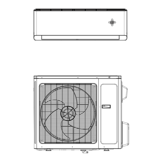
Service Manual Part Ⅰ : Technical Information 1. Summary Indoor Unit: SAP18HP230V1AH SAP24HP230V1AH Outdoor Unit: SAP18HP230V1AO SAP24HP230V1AO Remote Controller: YAG1FBF MODE ON/OFF Technical Information... - Page 5 Service Manual 2. ������� ����������� Model SAP18HP230V1A SAP24HP230V1A Product Code CB437001500 CB437001700 Rated Voltage 208/230 208/230 Power Supply Rated Frequency 50/60 50/60 Phases Power Supply Mode Outdoor Outdoor Cooling Capacity(Min~Max) Btu/h 18000(4094~21837) 22000(6800~30700) Heating Capacity(Min~Max) Btu/h 18000(4094~24566) 24000(6800~32000) Cooling Power Input(Min~Max)
- Page 6 Service Manual Model of Outdoor Unit SAP18HP230V1AO SAP24HP230V1AO Outdoor Unit Product Code CB437W01500 CB437W01700 ZHUHAI GREE DAIKIN DEVICE ZHUHAI LANDA COMPRESSOR Compressor Manufacturer/Trademark CO., LTD CO., LTD Compressor Model QXAT-D20zF030 QXAT-D20zF030 Compressor Oil RB68EP RB68EP Compressor Type Rotary Rotary Compressor L.R.A.
-
Page 7: Operation Characteristic Curve
Service Manual 2.2 Operation Characteristic Curve Cooling Heating Cooling Heating Condition Condition Indoor:DB 68°F Indoor:DB 81°F WB66°F Indoor air flow: Super High Indoor air flow: Super High Pipe length:24.6ft Pipe length:24.6ft Compressor Frequency(Hz) Compressor Frequency(Hz) 2.3 Capacity Variation Ratio According to Temperature Cooling Heating Condition... -
Page 8: Cooling And Heating Data Sheet In Rated Frequency
Service Manual 2.4 Cooling and Heating Data Sheet in Rated Frequency Cooling: Pressure of gas pipe Inlet and outlet pipe Rated cooling Compressor connecting indoor temperature of heat Fan speed of Fan speed of condition(°F) (DB/WB) Model revolution and outdoor unit exchanger indoor unit outdoor unit... -
Page 9: Noise Curve
Service Manual 2.5 Noise Curve Heating Cooling Compressor frequency(Hz) Super Middle Middle Super High Middle High High Indoor fan motor rotating speed Technical Information... -
Page 10: Outline Dimension Diagram
Service Manual 3. Outline Dimension Diagram 3.1 Indoor Unit 43 11/32 9 51/64 8 9/16 7 27/32 26 15/16 Φ2 3/4 Φ2 3/4 1 11/16 Unit: inch 3 1/8 6 1/16 Technical Information... -
Page 11: Outdoor Unit
Service Manual 3.2 Outdoor Unit 14 9/16 16 13/16 39 3/8 Unit:inch Technical Information... -
Page 12: Refrigerant System Diagram
Service Manual 4. Refrigerant System Diagram 4. Refrigerant System Diagram INDOOR UNIT OUTDOOR UNIT GAS SIDE 3-WAY VALVE 4-Way valve Discharge HEAT EXCHANGE (EVAPORATOR) Accumlator Suction COMPRESSOR HEAT EXCHANGE (CONDENSER) Intercooler LIQUID SIDE Strainer Strainer Strainer Electronic Capillary Strainer 2-WAY VALVE expansion valve COOLING... -
Page 13: Electrical Part
Service Manual 5. Electrical Part 5.1 Wiring Diagram ●Instruction Symbol Symbol Color Symbol Symbol Color Symbol Name White Green Jumper cap Yellow Brown COMP Compressor Blue Grounding wire YEGN Yellow/Green Black Violet Orange Note: Jumper cap is used to determine fan speed and the swing angle of horizontal lover for this model. ●... - Page 14 Service Manual ● Outdoor Unit SAP18HP230V1AO 63610000440 SAP24HP230V1AO 600007000653 These wiring diagrams are subject to change without notice; please refer to the one supplied with the unit. Technical Information...
-
Page 15: Pcb Printed Diagram
Service Manual 5.2 PCB Printed Diagram Indoor Unit ● Top view Name Neutral wire Needle stand for indoor fan Auto button Up&down swing motor left&right swing motor Interface of temperature sensor Terminal for display board connection Terminal of jumper cap Communication wire Connect earthing wire(only for the mode with this function) - Page 16 Service Manual Outdoor Unit ● Top view Terminal of compressor wire Terminal of low pressure protection Terminal of compressor overload protection Te r m i n a l o f o u t d o o r temperature sensor Terminal of outdoor fan Terminal of 4-way valve Communication wire with indoor unit...
- Page 17 Service Manual ● Top view Name Interface of compressor Interface of temperature sensor Terminal of compressor overload protection Low-temperature cooling sensor Cooling A valve Cooling B valve Interface of outdoor motor Interface of 2-way valve Interface of 4-way valve Terminal of chassis electric heating Communication wire with indoor unit...
-
Page 18: Function And Control
Service Manual 6. Function and Control 6.1 Remote Controller Introduction Buttons on Remote Controller ON/OFF button FAN button ON/OFF button MODE button FAN button +/- button MODE button TURBO button +/- button button TURBO button button button CLOCK button button TIMER ON/ TIMER OFF button CLOCK button... - Page 19 ATUO Service Manual 2. FAN button Low fan Medium-low fan Medium fan Medium-high fan High fan Press this button, Auto, Low, Medium-low, Medium, Medium-high, High speed can be circularly selected. After powered on, Auto fan speed is default. Under DRY mode, Low fan speed only can be set up. ATUO Note: It’s Low fan speed under Dry mode.
- Page 20 Service Manual 10. TEMP button Press this button, you can see indoor set temperature, indoor ambient temperature or outdoor ambient temperature on indoor unit’s display. The setting on remote controller is selected circularly as below: no display When selecting " "...
- Page 21 Service Manual ●Sleep 3- the sleep curve setting under Sleep mode by DIY: (1) Under Sleep 3 mode, press "Turbo" button for a long time, remote control enters into user individuation sleep setting status, at this time, the time of remote control will display "1hour ", the setting temperature "88" will display the corresponding temperature of last setting ������������������������������������������������������������...
- Page 22 Service Manual 28.WIFI Function Press "MODE" and "TURBO" button simultaneously to turn on or turn off WIFI function. When WIFI function is turned on, the " WiFi" icon will be displayed on remote controller; press and hold "MODE" and "TURBO" buttons simultaneously for 10 seconds, remote controller will send WIFI reset code and then the WIFI function will be turned on.
-
Page 23: Operation Of Smart Control (Smart Phone, Tablet Pc) For Gree
������������������������������������ Install the APP according to its guidance. When successfully installed, your smart phone homepage will show this icon User of IOS system can search for the Gree Smart in Apple store to download the Apple version APP. ������ �������������������������... - Page 24 Service Manual Select "Add device" and enter the page of "Add device". T���������������������������������� Step 2: Select the correct network name and enter the password. Select the server (The server setting here must keep the same as the server setting in "Settings" mentioned below��������������������������������������������� ����������������������...
- Page 25 Service Manual ������������������������������������������������ ���������������� NOTE: �������������������������������������������������� . You should reconnect your �������������������������������� ������������������������������������������� APP, connect with the air conditioner hot spot or ������������������� . When connection is done, open the APP to use short-distance operation to control the air conditioner and then you can use the long-distance control.
- Page 26 Service Manual (4) If password is forgotten, you can reset the password with your email address. Tap "Forgot password" and enter the page "Forgot password". T������������������������������������ password and tap "OK" to log in. 2.Personal settings Purpose: Set name (device name, preset name, etc.) and images (device image) in order to identify a user easily. (1) Set device name �����������������������������������������������������������������...
- Page 27 Service Manual (2) Set preset name Step 1: Tap at the top right corner of the homepage "Device". Select "Add preset" and enter the page "Preset edit". Step 2: Choose the time. Tap "Name". As shown in the picture, its name is "baby room". For timer type, select "On". Then select the repeating days.
- Page 28 Service Manual to increase or decrease temperature. Tap to change working mode. Tap to enter the page of fan speed adjustment. and go around the circle to adjust fan speed. Step 2: Advanced settings to enter advanced settings. You may select "Air", "Dry", "Health", "Light", "Sleep" or "Energy saving". (2) Advanced control functions: Set scene;...
- Page 29 Service Manual Tap "Add scene" and edit the scene name, for example, "Back home". Add execution devices. to add commands. On the page "Select execution device", select the air conditioner named "babyroom". Then select "ON" or "OFF". Continue to select the next execution device as instructed above. Tap to set the interval.
- Page 30 Service Manual (3) Preset includes single-device preset and multi-device preset Single-device preset: This can preset a certain device to be On/Of���������� On the homepage "Device", take air conditioner "babyroom" as an example. Tap at the bottom of the page "babyroom". Then you will enter the page "Preset edit".
- Page 31 Service Manual (4) Link(This function is APPlicable to some models) ��������������������������������������������������������������� commands to realize devices linkage. Step 1: Set the parameters of master device (Select master device, select environment parameters, select master device status). at the top right corner of the homepage "Device". Select "Link" and enter the page "Add linkage". Tap "Device/Param" to enter the page "Select device".
- Page 32 Service Manual Tap the days below "Repeat" to select the repeating days. Then tap "Save". Step 3: Select "Execute command" Tap "Execute command" and enter the page "Select device". Tap the name of device that you want to control. Tap "ON" or "OFF" and then tap "Save" to complete the linkage. Tap "Save"...
- Page 33 Service Manual (5) Infrared control (only APPlicable to smart phones with infrared emitter). Function: Smart phone can be used as a remote controller. at the top right corner of the homepage "Device". Select "Infrared" and enter the page "Remote controller". Tap slide up to enter the page of advanced functions.
- Page 34 Service Manual Step 2: Another smart phone to be imported. Tap the model name and wait for the download. (2) Backup: T������������������������������� s information, including backup to cloud and backup list on the cloud. Backup to cloud Enter the "Menu" on the left and tap "Backup". Tap "Backup to cloud"...
- Page 35 Service Manual (3) Settings User can set vibration, message alerts, server, updates, etc. The server setting here must be the same as the server setting in ���������������� Otherwise, remote control will be invalid. (4) Feedback User can feedback suggestions to back-stage management for maintenance and development. Tap "Feedback".
-
Page 36: Operation Of Smart Control (Smart Phone, Tablet Pc)
Step 1: ��������������� APP mode in factory. Y���������������������������������������������������������������� conditioner mac address. Password is 12345678. gree-a gr-cn gr-dh gr-cn Step 2: Open APP and the screen will show the air conditioner that you just connected. Tap the name of this air conditioner on your phone to enter and realize short-distance control, as shown below�����������������������������������... - Page 37 Service Manual ������������� Android phones ������������ Step 1: Enter homepage "Device", and then tap at the top right corner. Select "Add device" and enter the page "Add device". T���������������������������������� Step 2: Tap "Next" in the First Step. Step 3: Select the wireless network of air conditioner. APP will show the password 12345678 (default password of the network of air conditioner).
- Page 38 Service Manual NOTE: �������������������������������������������������� . You should reconnect your ���������������������������������������������������������������� shall install this APP, connect with the air conditioner hot spot or wireless router of WiFi air conditioner. When connection is done, open the APP to use short-distance operation to control the air conditioner and then you can use the long-distance control. �������������...
- Page 39 Service Manual ����������������������������������������������� . 2 mins later, please conduct the ����������������������������������������������������������� Turbo buttons on your remote control for 10 seconds and until you hear the beep. Wrong server selection will cause long-distance control invalid. Therefore, please make sure thatthe server selection when registering the account is the same as this one.
- Page 40 Service Manual 2.Personal settings Purpose: Set name (device name, preset name, etc.) and images (device image) in order to identify a user easily. (1) Set device name ���������������������������������������������������������������� the air condtioner mac address. Step 1: T������������������������������������������� Tap "Image" to select the source of image.
- Page 41 Service Manual (2) Set preset name Step 1: Tap at the top right corner of the homepage "Device". Select "Add preset" and enter the page "Preset edit". Step 2: Choose the time. Tap "Name". As shown in the picture, its name is "baby room". For timer type, select "On". Then select the repeating days.
- Page 42 Service Manual Tap "babyroom" and enter the page of air conditioner control. Tap to turn on the control switch. to increase or decrease temperature. Tap to change working mode. Tap to enter the page of fan speed adjustment. and go around the circle to adjust fan speed. Step 2: Advanced settings to enter advanced settings.
- Page 43 Service Manual Continue to select the next execution device as instructed above. Tap to set the interval. Tap "Save". Tap the scene picture displayed on homepage "Device" to send the command. Then the scene "Back home" will be in execution. You may view the execution condition of the scene. (3) Preset includes single-device preset and multi-device preset Single-device preset: This can preset a certain device to be On/Of�����������...
- Page 44 Service Manual Tap "Name" to customize the preset name. Preset device can’t be selected and it will default to "babyroom". Select "On" for the timer type. Select repeating days to complete the preset. Multi-device preset: ������������������������������������� Please refer to the instructions as how to set preset time, name, timer type and repeating days for a single device. Tap "Preset device"...
- Page 45 Service Manual Tap "Temperature" to enter the page "Select temperature parameter". Slide up or down to adjust temperature. Tap "Upper limit" or "Lower limit". Tap "Mode" and "On/Off" to select the status of master device. Then tap "Save". Step 2: Set time parameter for linkage. Tap "Time parameter" to enter the page "Set time". Slide rightwards to turn on the setting time.
- Page 46 Service Manual Tap the name of device that you want to control. Tap "ON" or "OFF" and then tap "Save" to complete the linkage. Tap "Save" and then repeat the above steps to set linkage of several scenes. 4.Menu functions Menu functions (Share, Set, History, Feedback) (1) Share: T������������������������...
- Page 47 Service Manual Step 2: Another smart phone to be imported. Tap the model name and wait for the download. Notice: This function requires that the two phones are of the same operating system. They are either Android phones or Apple phones,and are connecting to the same wireless router.
- Page 48 Service Manual (3) Settings User can set vibration, message alerts, server, updates, etc. The server setting here must be the same as the server setting in ����������������� Otherwise, remote control will be invalid. (4) Help Please refer to “Help” of APP for the instruction of the latest functions. Technical Information...
-
Page 49: Brief Description Of Modes And Functions
Service Manual 6.4 Brief Description of Modes and Functions 1. Temperature Parameters ◆ Indoor preset temperature (T preset ◆ Indoor ambient temperature (T amb. 2. Basic Functions Once energized, in no case should the compressor be restarted within less than 3 minutes. In the situation that memory function is available, �����������������������������������������������������������������... - Page 50 Service Manual ◆ When compressor is running (not including each malfunction and protection): a.When outdoor ambient temperature≥20°C(68°F) and indoor fan speed is low or medium, the fan speed will turn to high; if indoor fan speed is high or super high, it will keep the same. b.When outdoor ambient temperature≤18°C(64.4°F) , the fan speed will resume set fan speed.
- Page 51 Service Manual c.For heating and cooling unit, when 22°C(71.6°F)<Tindoor ambient<26°C(78.8°F) (for cooling only unit, 22°C(71.6°F)<Tindoor ����������������������������������������������������������������� ② Protection a. In cooling operation, protection is the same as that under the cooling mode; b. In heating operation, protection is the same as that under the heating mode; c.
- Page 52 Service Manual 1. In cooling mode: 1.1 When the initial set temperature is16-23°C(60.8~73.4°F),the temperature will rise 1°C(1.8°F) by every hour after sleep function is set;the temperature will not change after rising 3°C(5.4°F) ;after running for 7hours,the temperature will decrease1°C(1.8°F) and it will not change after that.
- Page 53 Service Manual 1. Under heating mode: auto speed under heating or auto heating mode: a. When T ≤T +1°C(1.8°F), indoor fan will operate at high speed; amb. preset b. When T +1°C(1.8°F)<T <T +3°C(5.4°F), indoor fan will operate at medium speed; preset amb.
-
Page 54: Part Ⅱ : Installation And Maintenance
Service Manual Part Ⅱ : Installation and Maintenance 7. Notes for Installation and Maintenance Safety Precautions: 10. If the power cord or connection wire is not long enough, please get the specialized power cord or connection wire Important! from the manufacture or distributor. Prohibit prolong the wire by yourself. - Page 55 Service Manual Main Tools for Installation and Maintenance 1. Level meter, measuring tape 2. Screw driver 3. Impact drill, drill head, electric drill 4. Electroprobe 5. Universal meter 6. Torque wrench, open-end wrench, inner hexagon spanner (hex wrenches) 7. Electronic leakage detector 8.
-
Page 56: Installation
Service Manual 8. Installation 8.1 Installation Dimension Diagram Installation and Maintenance... - Page 57 Service Manual Installation procedures Start installation Preparation before installation Read the requirements select installation Prepare tools for electric connection location Select indoor unit Select outdoor unit installation location installation location Install the support of outdoor unit Install wall-mounting (select it according to the actual situation) frame, drill wall holes Connect pipes of indoor Fix outdoor unit...
-
Page 58: Installation Parts-Checking
Service Manual 8.2 Installation Parts-checking 8.4 Electric Connection Requirement Name Name 1. Safety Precaution Indoor unit Sealing gum (1) Must follow the electric safety regulations when installing Outdoor unit Wrapping tape the unit. Support of outdoor (2) ���������������������������� Connection pipe unit power supply circuit and air switch. - Page 59 Service Manual in the holes. 5. Connect the Pipe of Indoor Unit (3) Fix the wall-mounting frame on the wall with tapping screws (1) Aim the pipe joint at the corresponding bellmouth.(As show (ST4.2X25T�������������������������� in Fig.5) pulling the frame. If the plastic expansion particle is loose, (2) Pretightening the union nut with hand.
- Page 60 Service Manual 7. Connect Wire of Indoor Unit 8. Bind up Pipe (1) Open the panel, remove the screw on the wiring cover and (1) Bind up the connection pipe, power cord and drain hose then take down the cover.(As show in Fig.11) with the band.(As show in Fig.14) (2) Reserve a certain length of drain hose and power cord Screw...
-
Page 61: Installation Of Outdoor Unit
Service Manual 8.6 Installation of Outdoor Unit Refer to the following table for wrench moment of force: Tightening torque(N . m) 1. Fix the Support of Outdoor Unit(Select it according to Hex nut diameter(mm) the actual installation situation) Φ6 15~20 Φ9.52 30~40 (1) Select installation location according to the house structure. -
Page 62: Vacuum Pumping And Leak Detection
Service Manual Note: 2. Leakage Detection (1) With leakage detector: (1) The through-wall height of drain hose shouldn't be higher Check if there is leakage with leakage detector. than the outlet pipe hole of indoor unit.(As show in Fig.25) (2) With soap water: (2) Slant the drain hose slightly downwards. -
Page 63: Wired Controller
Service Manual 8.9 Wired Controller If the product you bought is equipped with wired controller, please refer to the following introductions of wired controller. 1.Displaying Part Fig1.1.1 Outline of wired controller 1.1 LCD Display of Wired Controller Fig.1.1.2 LCD display 1.2 Instruction to LCD Display Description Symbols... - Page 64 Service Manual Lock function Shield functions (Button operation, temperature setting, On/Off operation,Mode setting are SHIELD disabled by the remote monitoring system.) TURBO Turbo function state Memory function (The indoor unit resumes the original setting state after power failure and MEMORY then power recovery) It blinks under on state of the unit without operation of any button SAVE...
- Page 65 Service Manual 3 Operation Instructions 3.1 On/Off Press On/Off to turn on the unit and turn it off by another press. Note: The state shown in Fig.3.1.1 indicates the “Off” state of the unit after power on. The state shown in Fig.3.1.2 indicates the “On” state of the unit after power on.
- Page 66 Service Manual • Timer off setting: Under on-state of the unit without timer setting, if Timer button is pressed, LCD will display xx. Hour,with OFF blinking. In this case, press▲ or ▼ button to adjust timer on and then press T�������� •...
- Page 67 Service Manual Timer range: 0.5-24hr. Every press of ▲or ▼ will make the set time increased or decreased by 0.5hr. If either of them is pressed continuously, the set time will increase/ decrease by 0.5hr every 0.5s. 3.6 Swing Setting Swing On: Press Function under on state of the unit to activate the swing function.
- Page 68 Service Manual Turn off the unit,without Sleep Press Function repeatedly unitll Press Enter/Cancel to activated the Sleep function activated go to the Sleep setting status function Press Enter/Cancel to cancel this Press Function repeatedly unitll go to the Fig.3.7.1. Sleep Setting setting Sleep function again 3.8 Turbo Setting...
- Page 69 Service Manual 3.9 E-heater Setting E-heater (auxiliary electric heating function): In the Heating mode, E-heater is allowed to be turned on for improvement of effciency. Once the wired controller or the remote controller enters the Heating mode, this function will be turned on automatically. Press Function in the Heating mode to enter the E-heater setting interface and then press Enter/Cancel to cancel this function.
- Page 70 Service Manual Notes: (1)When the Blow function is activated, if turning off the unit by pressing On/Off or by the remote controller, the indoor fan will run at the low fan speed for 2 min, with “BLOW” displayed on the LCD. While, if the Blow function is deactivated, the indoor fan will be turned off directly.
- Page 71 Service Manual Fig.4.2 Fig.4.2 Fig.4.2 shows the installation steps of the wired controller, but there are some issues that need your attention. �������������������������� f the power supply of the wire buried in the installation hole, that is, no operation is allowed with electricity during the whole installation.
- Page 72 Service Manual 5 Errors Display If there is an error occurring during the operation of the system, the error code will be displayed on the LCD, as show in Fig.5.1. If multi errors occur at the same time, their codes will be displayed circularly. Note: In event of any error, please turn off the unit and contact the professionally skilled personnel.
-
Page 73: Maintenance
Service Manual 9. Maintenance 9.1 Error Code List Display Method of Outdoor Display Method of Indoor Unit Unit Indicator has 3 kinds of Indicator Display (during display status and during Malfunction blinking, ON 0.5s and OFF Dual-8 A/C status Possible Causes blinking, ON 0.5s and OFF Name 0.5s) - Page 74 Service Manual Display Method of Outdoor Display Method of Indoor Unit Unit Indicator has 3 kinds of Indicator Display (during display status and during Malfunction blinking, ON 0.5s and OFF Dual-8 A/C status Possible Causes blinking, ON 0.5s and OFF Name 0.5s) Code...
- Page 75 Service Manual Display Method of Outdoor Display Method of Indoor Unit Unit Indicator has 3 kinds of Indicator Display (during display status and during Malfunction blinking, ON 0.5s and OFF Dual-8 A/C status Possible Causes blinking, ON 0.5s and OFF Name 0.5s) Code...
- Page 76 Service Manual Display Method of Outdoor Display Method of Indoor Unit Unit Indicator has 3 kinds of Indicator Display (during display status and during Malfunction blinking, ON 0.5s and OFF Dual-8 A/C status Possible Causes blinking, ON 0.5s and OFF Name 0.5s) Code...
- Page 77 Service Manual Display Method of Outdoor Display Method of Indoor Unit Unit Indicator has 3 kinds of Indicator Display (during display status and during Malfunction blinking, ON 0.5s and OFF Dual-8 A/C status Possible Causes blinking, ON 0.5s and OFF Name 0.5s) Code...
- Page 78 Service Manual Display Method of Outdoor Display Method of Indoor Unit Unit Indicator has 3 kinds of Indicator Display (during display status and during Malfunction blinking, ON 0.5s and OFF Dual-8 A/C status Possible Causes blinking, ON 0.5s and OFF Name 0.5s) Code...
- Page 79 Service Manual Display Method of Indoor Unit Display Method of Outdoor Unit Indicator Display (during Indicator has 3 kinds of display blinking, ON 0.5s and OFF status and during blinking, ON Dual-8 Malfunction A/C status Possible Causes 0.5s) 0.5s and OFF 0.5s Code Name Operation...
-
Page 80: Procedure Of Troubleshooting
Service Manual 9.2 Procedure of Troubleshooting Indoor unit 1. Malfunction of Temperature Sensor F1, F2 Main detection points: ● Is the wiring terminal between the temperature sensor and the controller loosened or poorly contacted? ● Is there short circuit due to trip-over of the parts? ●... - Page 81 Service Manual 2. Malfunction of Blocked Protection of IDU Fan Motor H6 Start Turn the fan blades by hand under power-off condition Adjust the motor and blade Whether the fan blades assembly so that rotor can run can run smoothly? smoothly.
- Page 82 Service Manual 3. Malfunction of Protection of Jumper Cap C5 Main detection points: ● Is there jumper cap on the mainboard? ● Is the jumper cap inserted correctly and tightly? ● The jumper is broken? ● The motor is broken? ����������������������������...
- Page 83 Service Manual 4. Malfunction of Overcurrent Protection E5 Main detection points: ● �������������������������� ● Is the supply voltage too low with overload? ● Hardware trouble? Malfunction diagnosis process: Start �������������������� Is malfunction Is the supply voltage unstable of the rated voltage on the nameplate eliminated ����������...
- Page 84 Service Manual 5. Communication Malfunction E6 Start Cut off power supply. Check if connection line of IDU and ODU and the wire inside electric box are correctly connected. Connect the line Correct connection? according to Malfunction eliminated? wiring diagram. Main board matches Match correctly with display board? Main board of Malfunction eliminated?
- Page 85 Service Manual 6. Malfunction of detecting plate(WIFI) JF 5. Malfunction of detecting plate(WIFI) JF Start check if the connection wire are correctly connected detecting Replace the plate with the same model Is malfunction eliminated Replace the mainboard with the same model The end Installation and Maintenance...
- Page 86 Service Manual Outdoor Unit 1. Capacity charging malfunction (outdoor unit malfunction) (AP1 below means control board of outdoor unit) Main detection points: ● Detect if the voltage of L and N terminal of XT wiring board is between 210VAC-240VAC by alternating voltage meter; ●...
- Page 87 Service Manual 2. IPM protection(H5), desynchronizing malfunction(H7), overcurrent of compressor phase current (P5) (AP1 below means control board of outdoor unit) Main detection points: ● Is voltage input within the normal range ● If the control board AP1 is well connected with compressor COMP? If they are loosened? If the connection sequence is correct? ●...
- Page 88 Service Manual 3. High temperature and overload protection (E8)(AP1 below means control board of outdoor unit) Main detection points: ● If the outdoor ambient temperature is in normal range; ● If the indoor and outdoor fan are running normally; ● If the radiating environment of indoor and outdoor unit is good. E8 is displayed Normal protection, please If the outdoor...
- Page 89 Service Manual 4. Start-up failure (LC) (AP1 below means control board of outdoor unit) Main detection points: ● If the compressor wiring is correct? ● ���������������������� ● If the compressor is damaged? ● If the refrigerant charging amount is too much? Turn on the unit The stop time is not sufficient and If the stop time of compressor...
- Page 90 Service Manual 5. Overload and high discharge temperature malfunction Main detection points: ● If the electronic expansion valve is connected well? Is the electronic expansion valve damaged? ● If the refrigerant is leaked? ● The compressor overload protection terminal is not connected well with the mainboard? ●...
- Page 91 Service Manual H3 or E4 is displayed 30min after power off the unit If the overload protector SAT is well connected? Under ambient temperature, test the resistance of overload protector with ohmmeter; resistance value should be<1000ohm Connect wire If the wiring terminal FA of electronic according to wiring expansion valve is well connected? diagram...
- Page 92 Service Manual 6. PFC (correction for power factor) malfunction (outdoor unit malfunction) Main detection points: ● Check if power plug is connected well with the socket ● Check if the reactor of outdoor unit is damaged? Malfunction diagnosis process: start If power plug is connected Is the malfunction Connect the plug correctly...
- Page 93 Service Manual 7. Communication malfunction (E6) Main detection points: ● Check if the connection wire and the built-in wiring of indoor and outdoor unit are connected well and without damage; ● If the communication circuit of indoor mainboard is damaged? If the communication circuit of outdoor mainboard (AP1) is damaged? Malfunction diagnosis process: If the unit operates normally before malfunction...
-
Page 94: Troubleshooting For Normal Malfunction
Service Manual 9.3 Troubleshooting for Normal Malfunction 1. Air Conditioner Can't be Started Up Possible Causes Discriminating Method (Air conditioner Status) Troubleshooting ������������������������� No power supply, or poor After energization, operation indicator isn’t bright wait for power recovery. If not, check power connection for power plug and the buzzer can't give out sound supply circuit and make sure the power plug is... - Page 95 Service Manual 4. ODU Fan Motor Can't Operate Possible causes Discriminating method (air conditioner status) Troubleshooting Connect wires according to wiring diagram to Wrong wire connection, or poor Check the wiring status according to circuit make sure all wiring terminals are connected connection diagram ���...
-
Page 96: Exploded View And Parts List
Service Manual 10. Exploded View and Parts List 10.1 Indoor Unit MODE ON/OFF The component picture is only for reference; please refer to the actual product. Installation and Maintenance... - Page 97 Service Manual Part Code Description SAP18HP230V1AH SAP24HP230V1AH Product Code CB437N01500 CB437N01700 Front Panel(low display) 20000300059T 20000300059T Filter Sub-Assy 11012007 11012007 Front Case Sub-Assy 0000020006401 0000020006401 Axile Bush 10542036 10542036 Guide Louver 10512503 10512503 Ring of Bearing 26152025 26152025 O-Gasket of Cross Fan Bearing 76512203 76512203 Cross Flow Fan...
-
Page 98: Outdoor Unit
Service Manual 10.2 Outdoor Unit Installation and Maintenance... - Page 99 Service Manual Part Code Description SAP18HP230V1AO SAP24HP230V1AO Product Code CB437W01500 CB437W01700 Front Grill 01473050 01473050 Fan Motor 15010400000102 15010400000102 Radiator 49015215 4901521501 Main Board 300027000040 300027000224 Electric Box Assy 100002000485 100002000598 Terminal Board Support sub-assy 01715016 01715016 Terminal Board 42010255 42010255 Handle 26233053...
-
Page 100: Removal Procedure
Service Manual 11. Removal Procedure Caution: discharge the refrigerant completely before removal. 11.1 Removal Procedure of Indoor Unit Step Procedure ������� Panel Open the panel. Loosen the clasp shown and �������������������� outwards to remove them. ������������� 2.Remove horizontal louver Push out the axile bush on horizontal louver. - Page 101 Service Manual Step Procedure 3.Remove display and panel Screws Screws that are locking the display board. Display Separate the display board from the front Panel panel. Open the front panel; separate the panel �������������������� front panel and then removes the front panel.
- Page 102 Service Manual Step Procedure 7.Remove cold plasma generator Cold plasma generator Screws that are locking the cold plasma Screw generator.Separate the display board from the evaporator assy. 8.Remove temperature sensor and grounding wire Temperature sensor Grounding wire Cut off the tieline which binding the temperature sensor and grounding wire on the evaporator, and then pull out the indoor tube temperature sensor from the...
- Page 103 Service Manual Step Procedure 11.Electric box assy ������������������ assy and then remove the electric box assy. Electric box assy Screw 12.Remove connection pipe clamp Screw Connection pipe clamp At the back of the unit, remove the ����������������� and then remove the connection pipe clamp.
- Page 104 Service Manual Step Procedure ������������������� Motor clamp ������������������ Screws and then remove the motor clamp. Remove the screws at the connection �������������������� ������������������� to remove them. Motor Screw ����� Remove the bearing holder sub-assy. Holder sub-assy Installation and Maintenance...
-
Page 105: Removal Procedure Of Outdoor Unit
Service Manual 11.2 Removal Procedure of Outdoor Unit Warning: Be sure to wait for a minimum of 20 minutes after turning off all power supplies and discharge the refrigerant completely before removal. Steps Procedure 1.Remove handle Twist off the screws used for fixing the handle,pull the handle up ward to remove it. - Page 106 Service Manual Steps Procedure 4.Remove grille and panel Twist off the screws connecting the grille and panel, and then remove the grille. Twist off the screws connecting the panel, chassis and motor support with screwd-river, and then remove the panel. grille panel 5.Remove right side plate...
- Page 107 Service Manual Steps Procedure 7.Remove electric box electric box Twist off the screws on electric box, cut off the tieline with scissors or pliers, pull out the wiring terminal, pull it upwards to remove the electric box. Twist off the screws on electric box (fireproofing) electric box with screwdriver, and then remove the electric (fireproofing)
- Page 108 Service Manual Steps Procedure 9.Remove motor support Twist off the tapping screws fixingthe motor support, pull it upwardsand then remove the motor support. motor support 10.Remove isolation sheet Twist off the screws connecting isolation sheet and end plate of condenser and chassis, and then remove the isolation sheet.
- Page 109 Service Manual Steps Procedure 12.Remove gas valve and liquid valve Twist off the 2 bolts fixing the valve sub-assy. Unsolder the soldering joint between gas valve and air-return pipe and then remove the gas valve.(note: when unsoldering the soldering joint, wrap the gas valve with wet cloth completely to gas valve avoid the damage to valve, and release all...
- Page 110 Service Manual Steps Procedure 15.Remove left side plate Twist off the screws connecting the left side plate and chassis with screwdriver, and then remove the left side plate. left side plate 16.Remove chassis and condenser Pull it upwards to separate the chassis and condenser.
-
Page 111: Appendix
Service Manual Appendix: Appendix 1: Reference Sheet of Celsius and Fahrenheit Conversion formula for Fahrenheit degree and Celsius degree: Tf=Tcx1.8+32 Set temperature Fahrenheit Fahrenheit Fahrenheit display Fahrenheit display Fahrenheit display Fahrenheit Celsius (℃) Celsius (℃) Celsius (℃) temperature temperature temperature (℉)... -
Page 112: Appendix 3: Pipe Expanding Method
Service Manual Appendix 3: Pipe Expanding Method Pipe Note: Pipe cutter Improper pipe expanding is the main cause of refrigerant leakage.Please expand the pipe according to the following steps: Leaning Uneven Burr A:Cut the pip ������������������������������������������ ● Cut the required pipe with pipe cutter. B:Remove the burrs Pipe Shaper... -
Page 113: Appendix 4: List Of Resistance For Temperature Sensor
Service Manual Appendix 4: List of Resistance for Temperature Sensor Resistance Table of Ambient Temperature Sensor for Indoor and Outdoor Units(15K) Temp( ) Resistance(k ) Temp( ) Resistance(k ) Temp( ) Resistance(k ) Temp( Resistance(k ) 138.1 18.75 3.848 1.071 128.6 17.93 3.711... - Page 114 Service Manual Resistance Table of Tube Temperature Sensors for Indoor and Outdoor (20K) Temp( ) Resistance(k ) Temp( ) Resistance(k ) Temp( ) Resistance(k ) Temp( Resistance(k ) 181.4 25.01 5.13 1.427 171.4 23.9 4.948 1.386 162.1 22.85 4.773 1.346 153.3 21.85 4.605...
- Page 115 Service Manual Resistance Table of Discharge Temperature Sensor for Outdoor(50K) Temp( ) Resistance(k ) Temp( ) Resistance(k ) Temp( ) Resistance(k ) Temp( Resistance(k ) 853.5 18.34 4.754 799.8 93.42 17.65 4.609 89.07 16.99 4.469 703.8 84.95 16.36 4.334 660.8 81.05 15.75 4.204...
- Page 116 JF00303049 PTAC DIRECT SALES, INC. 185 S. KIMBALL AVE., SUITE 130 SOUTHLAKE, TX 76092 877.454.7822 Cat No: GREE_SAPPHIRE_SERVICE_18-24MBH_111617...
Need help?
Do you have a question about the SAP24HP230V1A and is the answer not in the manual?
Questions and answers