Advertisement
Quick Links
Advertisement

Subscribe to Our Youtube Channel
Related Manuals for Gree GWH12UC-D3DNA4A


Summary of Contents for Gree GWH12UC-D3DNA4A
- Page 1 Change for Life Service Manual GREE ELECTRIC APPLIANCES,INC.OF ZHUHAI...
- Page 11 Condition Condition Indoor:DB 68°F Indoor:DB81°F WB66°F Indoor air flow:Super High Indoor air flow: Super High Pipe length:24.6 ft Pipe length:24.6 ft Compressor Speed(rps) Compressor Speed(rps) Condition Condition Indoor:DB 68°F Indoor:DB 81°F WB66°F Indoor air flow: Super High Indoor air flow: Super High Pipe length:24.6ft Pipe length:24.6ft Compressor Frequency(Hz)
- Page 12 Condition Condition Indoor:DB 68°F Indoor:DB81°F WB66°F Indoor air flow:Super High Indoor air flow: Super High Pipe length:24.6 ft Pipe length:24.6 ft 89.6 100.4 107.6 118.4 17.6 44.6 Outdoor temp(°F) Outdoor temp(°F)
- Page 13 Indoor side noise Outdoor side noise 09K/12K 09K/12K Heating Cooling Super Middle Middle Super Compressor frequency(Hz) High Middle High High Indoor fan motor rotating speed Heating Cooling Compressor frequency(Hz) Super Middle Middle Super High Middle High High Indoor fan motor rotating speed...
- Page 14 3 1/7...
-
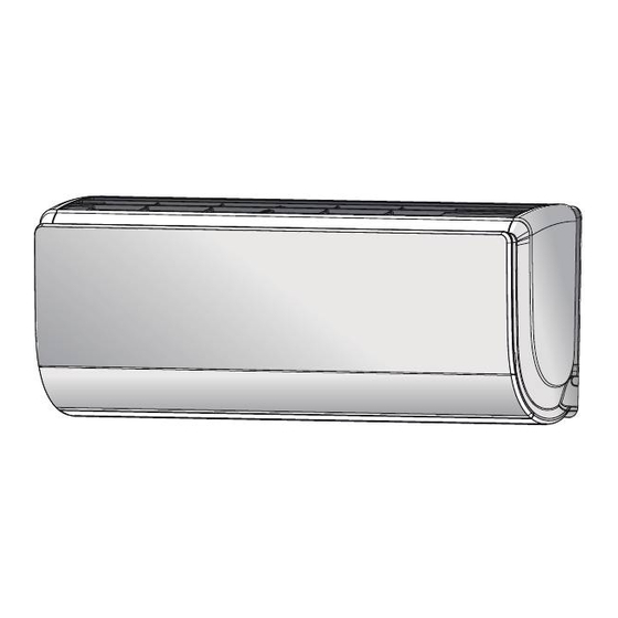
Page 16: Indoor Unit
INDOOR UNIT OUTDOOR UNIT GAS SIDE 3-WAY VALVE 4-Way valve Discharge HEAT EXCHANGE (EVAPORATOR) Accumlator Suction COMPRESSOR HEAT EXCHANGE (CONDENSER) Intercooler LIQUID SIDE Electron Strainer Strainer Strainer Capillary Strainer 2-WAY VALVE expansion valve COOLING HEATING... - Page 18 L1’ L2’...
- Page 20 14 15...
- Page 21 Terminal of compressor wire Terminal of low pressure protection Terminal of compressor overload protection Te r m i n a l o f o u t d o o r temperature sensor Terminal of outdoor fan Terminal of 4-way valve Communication wire with indoor unit Power supply live wire...
- Page 22 Humidify Health ON/OFF button +/- button Cool button Heat button Fan button I FEEL button up down swing button Mode button Left right swing button T-ON/T-OFF button Clock button Humidity button/Health button X-fan button Air button Light button Sleep button WIFI button...
- Page 23 Set fan speed Send signal Operation mode battery power Auto mode WIFI humidity functions Cool mode INTELLIGENT Temp.display type Healthy mode Dry mode Set temperature Fan mode Heat mode Up & down swing Set time Left & right swing heating function HOUR ON OFF Turbo fan speed child lock...
- Page 24 no display (stops at current position) AUTO COOL HEAT no display (horizontal louvers stops at current position)
- Page 25 cancel INTELLIGENT INTELLIGENT cancel cancel...
- Page 26 signal sender battery reinstall remove Cover of battery box battery level...
- Page 34 ① ⑤ ④ ② ③...
- Page 35 Horizontal louver postion diagrammatic sketch Initial stauts after reset is finished Lower swing Upper swing...
- Page 39 1. Compensation function of input parameters According to the structure of wall-mounting unit, considering the comfortability for operation, indoor ambient temperature when the compressor is at OFF status is higher than set temperature under heating mode. 2. Control of detecting the availability of parameters For ensuring the safety and reliability of operation, please insert the outdoor discharge temperature sensor into the corresponding temperature sensor bushing to make sure that the control system can detect system discharge temperature accurately.
- Page 40 11.2 Under cooling or drying mode, if T <6, the operation frequency of compressor may increase or decrease; inner tube 11.2.1 If the unit is stopped because of freeze protection for 6 times successively, it can’t resume operation automatically and the malfunction will be displayed continuously, which can only be resumed by pressing ON/OFF button.
- Page 43 Space to the wall At least 5 8/9 inch At least 5 8/9 inch Space to the wall Drainage pipe...
- Page 44 Start installation Preparation before installation Read the requirements select installation Prepare tools for electric connection location Select indoor unit Select outdoor unit installation location installation location Install the support of outdoor unit Install wall-mounting (select it according to the actual situation) frame, drill wall holes Connect pipes of indoor Fix outdoor unit...
-
Page 46: Outlet Pipe
Wall Wall Mark in the middle of it Level meter Space Space to the to the Open-end wrench wall wall above above Union nut 6 inch 6 inch Pipe Pipe joint Union nut Pipe Torque wrench Right Left Φ2 1/6 or 2 3/4inch Φ2 1/6 or 2 3/4inch Indoor pipe Rear piping hole... - Page 47 Screw Pane Wiring cover Indoor and outdoor power cord Indoor unit pipe Liquid pipe Band Drain hose Drain hose Connection pipe connection wire sleeve Band Indoor power cord L1’ L2’ green white black (yellow- (blue) (brown) green) Outdoor unit connection Indoor Outdoor Wall pipe...
- Page 48 Drain vent Chassis Outdoor drain join t Drain hose At least 3cm above the floor Cable-Crossing board 2 Connect to indoor unit Cable-Crossing board 1 handle Foot holes Cable-Crossing board 2 Connect to indoor unit L2' L2 L1 G Handle Wiring board Foot holes Valve Cover...
- Page 49 The drain hos can't raise upwards Wall U-shaped curve Drain hose The drain hose can't be fluctuant The water outlet can't be placed The drain hose in water can't be fluctuant The water outlet can't be fluctuant Liquid valve Piezometer Gas valve Valve cap Refrigerant charging...
- Page 50 Display Method of Outdoor Display Method of Indoor Unit Unit Indicator has 3 kinds of Indicator Display (during display status and during Malfunction blinking, ON 0.5s and OFF Dual-8 A/C status Possible Causes blinking, ON 0.5s and OFF Name 0.5s) Code 0.5s Display...
- Page 51 Display Method of Outdoor Display Method of Indoor Unit Unit Indicator has 3 kinds of Indicator Display (during display status and during Malfunction blinking, ON 0.5s and OFF Dual-8 A/C status Possible Causes blinking, ON 0.5s and OFF Name 0.5s) Code 0.5s Display...
- Page 52 Display Method of Outdoor Display Method of Indoor Unit Unit Indicator has 3 kinds of Indicator Display (during display status and during Malfunction blinking, ON 0.5s and OFF Dual-8 A/C status Possible Causes blinking, ON 0.5s and OFF Name 0.5s) Code 0.5s Display...
- Page 53 Display Method of Outdoor Display Method of Indoor Unit Unit Indicator has 3 kinds of Indicator Display (during display status and during Malfunction blinking, ON 0.5s and OFF Dual-8 A/C status Possible Causes blinking, ON 0.5s and OFF Name 0.5s) Code 0.5s Display...
- Page 54 Display Method of Outdoor Display Method of Indoor Unit Unit Indicator has 3 kinds of Indicator Display (during display status and during Malfunction blinking, ON 0.5s and OFF Dual-8 A/C status Possible Causes blinking, ON 0.5s and OFF Name 0.5s) Code 0.5s Display...
- Page 55 Display Method of Outdoor Display Method of Indoor Unit Unit Indicator has 3 kinds of Indicator Display (during display status and during Malfunction blinking, ON 0.5s and OFF Dual-8 A/C status Possible Causes blinking, ON 0.5s and OFF Name 0.5s) Code 0.5s Display...
- Page 56 Display Method of Indoor Unit Display Method of Outdoor Unit Indicator Display (during Indicator has 3 kinds of display blinking, ON 0.5s and OFF status and during blinking, ON Dual-8 Malfunction A/C status Possible Causes 0.5s) 0.5s and OFF 0.5s Code Name Display...
- Page 57 Troubleshooting for F1,F2 malfunction the wiring terminal between the temperature sensor and the controller loosened or poorly contacted? Insert the temperature sensor tightly Is malfunction eliminated Is there short circuit due to trip - over of the parts? Make the parts upright Is malfunction eliminated Is the...
- Page 58 Start Turn the fan blades by hand under power-off condition Adjust the motor and blade Whether the fan blades assembly so that rotor can run can run smoothly? smoothly. Turn unit on to check whether the malfunction is eliminated. Under power-off condition, Reinsert the wiring check whether the wiring terminal between indoor fan and main...
- Page 59 Troubleshooting for C5 malfunction Appearance of Is there jumper cap on the the jumper cap mainboard ? Assemble the jumper cap with the same model Is malfunction eliminated the jumper cap inserted correctly and tightly ? Insert the jumper cap tightly Is malfunction eliminated...
- Page 60 Troubleshooting for E5 malfunction Is the supply voltage unstable Normal fluctuation is within 10 % of the rated Malfunction is with big fluctuation? voltage on the nameplate eliminated Is the supply voltage too low Malfunction is Malfunction is Adjust the supply voltage to maintain it within with overload? eliminated normal range...
- Page 61 Start Cut off power supply. Check if connection line of IDU and ODU and the wire inside electric box are correctly connected. Connect the line Correct connection? according to Malfunction eliminated? wiring diagram. Main board matches Match correctly with display board? Main board of Malfunction eliminated? according to product IDU matches with that of ODU?
- Page 62 Turn on the unit and wait 1 minute Use AC voltmeter to measure the voltage on the two ends of electrolytic capacitor (see fig 30) Malfunction of Replace outdoor Voltage higher the outdoor mainboard than 200V? mainboard AP1 Measure the voltage input with AC voltmeter (see fig 30) Power supply is...
- Page 63 H5, H7 or P5 is displayed after turning on the unit Measure if the voltage The unit starts Repair power supply to make input is within 180~265V Restart the unit operation again the power voltage normal with AC voltmeter (see fig 30) The compressor Adjust it properly The unit starts...
- Page 64 E8 is displayed Normal protection, please If the outdoor Unit restarts use it after improving the ambient temperature is higher normally outdoor ambient temperature than 53℃? Improve the radiating environment If the radiating of indoor of unit (clean the heat exchanger Unit restarts and outdoor unit is good? and remove surrounding obstacles)
- Page 65 Turn on the unit The stop time is not sufficient and If the stop time of compressor the high and low pressure of system is more than 3min? is not balanced , please start the unit after 3min Check the connection situation of outdoor mainboard AP1 and If the compressor wire compressor COMP, and the...
- Page 67 H3 or E4 is displayed 30min after power off the unit If the overload protector SAT is well connected? Under ambient temperature, test the resistance of overload protector with ohmmeter; resistance value should be<1000ohm Connect wire If the wiring terminal FA of electronic according to wiring expansion valve is well connected? diagram...
- Page 68 start If power plug is connected Is the malfunction Connect the plug correctly well with the socket eliminated? Check the connection wire between reactor mainboard and situation of connection Reconnect the wire or Power on and If there is short circuit or the replace the connection Is the malfunction restart the unit...
- Page 69 If the unit operates normally before malfunction Check the connection wire according to the wiring diagram. Check built-in wiring If the connection wire of indoor and outdoor is connected well? unit Reconnect the wire or Replace the If the wiring is replace the connection wire damaged?
- Page 70 Test9 Test3 Test4 Test2 Test1 Test5 Test8 Tset7 Test6 Test10 Test11 Test12...
- Page 71 Turn on the unit and wait 1 minute Use DC voltmeter to measure the voltage on the two ends of electrolytic capacitor Fault with the voltage Replace the control testing circuit on Voltage higher than 200V? panel AP1 control panel AP1 Measure the AC voltage between terminal L and N on wiring board XT(power supply)
- Page 73 Energize and switch on Use AC voltmeter If the voltage Check the supply to measure the IPM protection between terminal L voltage and voltage between occurs after the and N on wiring terminal L and N machine has run for restore it to board XT is within a period of time?
- Page 74 Anti-high temperature, overload protection Normal protection, please use If the outdoor ambient temperature is it after improve the outdoor higher than 53 ºC? ambient temperature After the unit de- energized for 20min Improve the If the radiating of outdoor radiating environment of and indoor unit is well? unit...
- Page 75 Energize the unit and start it If the stop time is not enough and the If the stop time of compressor high and low pressure of system is not is more than 3min? balance , please start it after 3min Improve the connection situation If the compressor wire COMP(UVW) is of control board AP1 and...
- Page 76 Synchronism Synchronism after energize the unit occurred during and start it operation Check if the fan Replace fan If the stop time of If the outdoor fan works terminal OFAN is capacitor C1 compressor is more than normally? connected well 3min Replace Improve the radiating...
- Page 77 After the unit de-energized for 20min If the overload protector SAT is well connected? Under ambient temperature, test the resistance of overload protector with ohmic Connect wire If the wiring terminal FA of electron well with wiring expansion is well connected? diagram The resistance value of firs t 4 l e ad fo ot an d th e...
- Page 78 Start Check the connection wire of reactor (L) of outdoor unit and PFC capacity Replace connection If there is damaged If the malfunction is wire with circuit short circuit removed? diagram Remove PFC capacity and test resistance of two terminals Capacity is Re-energize short...
- Page 79 Start If the unit is operation normal before malfunction Check connection wire of indoor and outdoor unit with circuit diagram Check built- in wiring of Connection indoor and correct? outdoor unit Malfunction of Check connection circuit is wire of indoor and If the wiring is detected with outdoor unit with...
- Page 80 Start Test voltage value with Test 10 position in diagram with voltage meter Number jumping Test voltage value with Test 13 position in diagram with voltage meter Number jumping Outdoor unit Test voltage malfunction value with Test 11 position in diagram with voltage meter Number jumping...
- Page 98 1. Remove top cover Remove the screws connecting top cover, left and right side plate, as well as panel, to remove the top top cover cover. 2. Remove cable cross plate sub-assy and valve cover Remove the screws connecting cable cross plate cable cross sub-assy and right side plate, to remove the cable plate sub-assy...
- Page 99 4. Remove left side plate Remove the screws fixing left side plate and condenser support boa rd, to remove the left side plate. left side plate 5. Remove cross fan blade Remove the screw nut fixing cross fan blade, remove the gasket and spring cushion, to remove the cross fan blade.
- Page 100 7. Remove electric box assy electric box cove r Remove screws fixing electric box assy and mid-isolation board, loosen the bonding tie, pull off the electric box assy wiring terminal, lift to remove the electric box assy. 8. Remove electric reactor Remove the screws fixing electric reactor, to remove the electric reactor.
- Page 101 flash vaporizer assy 10. Remove flash vaporizer assy Remove the screws connecting mid-isolation board, lift to remove the flash vaporizer assy. 11. Remove four-way valve assy four-way valve assy Welding cut the spot weld of four-way valve assy, compressor air suction/discharging valve and condenser pipe outlet, lift to remove the four-way valve assy.
- Page 102 13. Remove compressor compressor Remove the three feet screwnuts fixing compressor, to remove the compressor. 14. Remove big and small valve assy Remove screws connecting condenser assy and chassis, to remove the condenser assy. Remove the screws fixing big and small valve, to small valve remove the valves.
- Page 103 1.Remove handle Twist off the screws used for fixing the handle,pull the handle up ward to remove it. handle 2.Remove top panel top panel Remove the screws connecting the top panel with the front panel and left&right side plate, and then remove the top panel. 3.Remove front side panel Loosen the screws connecting the front side panel and chassis.
- Page 104 4.Remove grille and panel Twist off the screws connecting the grille and panel, and then remove the grille. Twist off the screws connecting the panel, chassis and motor support with screwd-river, and then remove the panel. grille panel 5.Remove right side plate right side plate Twist off the screws connecting the right side plate and chassis, valve support and condenser,...
- Page 105 7.Remove electric box electric box Twist off the screws on electric box, cut off the tieline with scissors or pliers, pull out the wiring terminal, pull it upwards to remove the electric box. Twist off the screws on electric box (fireproofing) electric box with screwdriver, and then remove the electric (fireproofing)
- Page 106 9.Remove motor support Twist off the tapping screws fixingthe motor support, pull it upwardsand then remove the motor support. motor support 10.Remove isolation sheet Twist off the screws connecting isolation sheet and end plate of condenser and chassis, and then remove the isolation sheet. isolation sheet 11.Remove 4-way valve 4-way valve...
- Page 107 12.Remove gas valve and liquid valve Twist off the 2 bolts fixing the valve sub-assy. Unsolder the soldering joint between gas valve and air-return pipe and then remove the gas valve.(note: when unsoldering the soldering joint, wrap the gas valve with wet cloth completely to gas valve avoid the damage to valve, and release all refrigerant completely at first).
- Page 108 15.Remove left side plate Twist off the screws connecting the left side plate and chassis with screwdriver, and then remove the left side plate. left side plate 16.Remove chassis and condenser Pull it upwards to separate the chassis and condenser. condenser chassis...
- Page 110 Pipe Pipe cutter Leaning Uneven Burr Pipe Shaper Downwards Union pipe Pipe Hard mold Expander Pipe Smooth surface Improper expanding leaning damaged crack uneven surface thickness The length is equal...
- Page 111 Temp( ) Resistance(kΩ) Temp( ) Resistance(kΩ) Temp( ) Resistance(kΩ) Temp( Resistance(kΩ) 138.1 18.75 3.848 1.071 128.6 17.93 3.711 1.039 121.6 17.14 3.579 1.009 16.39 3.454 0.98 108.7 15.68 3.333 0.952 102.9 3.217 0.925 97.4 14.36 3.105 0.898 92.22 13.74 2.998 0.873 87.35 13.16...
- Page 112 Temp( ) Resistance(kΩ) Temp( ) Resistance(kΩ) Temp( ) Resistance(kΩ) Temp( Resistance(kΩ) 181.4 25.01 5.13 1.427 171.4 23.9 4.948 1.386 162.1 22.85 4.773 1.346 153.3 21.85 4.605 1.307 20.9 4.443 1.269 137.2 4.289 1.233 129.9 19.14 4.14 1.198 18.13 3.998 1.164 116.5 17.55 3.861...
- Page 113 Temp( ) Resistance(kΩ) Temp( ) Resistance(kΩ) Temp( ) Resistance(kΩ) Temp( Resistance(kΩ) 853.5 18.34 4.754 799.8 93.42 17.65 4.609 89.07 16.99 4.469 703.8 84.95 16.36 4.334 660.8 81.05 15.75 4.204 620.8 77.35 15.17 4.079 580.6 73.83 14.62 3.958 548.9 70.5 14.09 3.841 516.6 67.34...
Need help?
Do you have a question about the GWH12UC-D3DNA4A and is the answer not in the manual?
Questions and answers