
Related Manuals for Digigram ALP222e-Mic


Summary of Contents for Digigram ALP222e-Mic
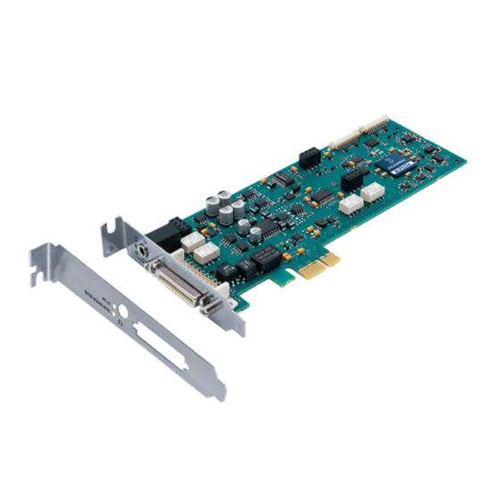
- Page 1 User Manual – ALP222e & ALP222e-Mic User Manual ALP222e & ALP222e-Mic Professional stereo sound cards May 2023...
-
Page 2: Table Of Contents
User Manual – ALP222e & ALP222e-Mic TABLE OF CONTENTS 1 INTRODUCTION 2 IMPORTANT NOTICE 3 BOX CONTENTS 4 GENERAL CHARACTERISTICS 4.1 Main hardware characteristics 4.2 Main software characteristics 4.3 Routing audio streams in the card 5 REQUIRED CONFIGURATION 5.1 Required hardware configuration 5.2 Necessary software configuration under Windows... - Page 3 User Manual – ALP222e & ALP222e-Mic 13.1 Configuration 13.2 Inputs 13.3 Outputs 13.4 Audio characteristics 13.5 Analog performances 13.6 Sample rate converter performance (SRC) 13.7 Connectors 13.8 Development environment 14 APPENDICES 14.1 ALP222e functional diagram 14.2 LED 14.3 Connectors and switches 14.4 Breakout cable diagram...
-
Page 4: Introduction
(4, 8 channels). Copyright 2022 Digigram. All rights reserved. No part of this manual may be reproduced without the prior consent of Digigram. This reservation includes photocopying, translating and/or reformatting the information contained in this manual. Everything possible has been done to ensure the greatest accuracy, however Diagram cannot be held liable for any error or omission and reserves the right to make modifications and improvements without prior... -
Page 5: Important Notice
User Manual – ALP222e & ALP222e-Mic 2 IMPORTANT NOTICE Certifications The product is currently being certified. This product has been designed in accordance with the following standards: EMC Directive 2014/30/EU. ● FCC Rules Part 15, Subpart B. ● To ensure compliance with the standards listed above, the following rules must be followed: The cable supplied must not be modified. -
Page 6: Box Contents
3 BOX CONTENTS Thank you for purchasing a DIGIGRAM sound card in the ALP-X range. The box contains: an ALP222e or ALP222e-Mic sound card equipped with a standard height bracket (full ● height: 120 mm), a low-profile bracket (79.2 mm) that can be fitted instead of the full-height bracket, ●... -
Page 7: General Characteristics
- clock source - frequency of the fallback internal clock - input and output gains, phantom power (ALP222e-Mic), RMS VU-meters with peak-meters - routing of inputs to outputs API for implementing the management of the card settings in a software application. - Page 8 User Manual – ALP222e & ALP222e-Mic Principle of the ALP222e on-board mixer Note: the stereo headphone output replicates the analog outputs.
-
Page 9: Required Configuration
User Manual – ALP222e & ALP222e-Mic 5 REQUIRED CONFIGURATION 5.1 Required hardware configuration There are no particular hardware restrictions in terms of PC on using the ALP card and its driver. The PC can have standard height or low profile PCIe card slots. The ALP card can in particular be used in 2U racks or reduced size PCs, by using the smaller bracket instead of the standard height bracket that is fitted by default. - Page 10 User Manual – ALP222e & ALP222e-Mic Select “Change advanced power settings”. Select “PCI Express”, “Link State Power Management”, and select “Off” for the setting. Click on Ok to validate...
-
Page 11: Necessary Software Configuration Under Windows
User Manual – ALP222e & ALP222e-Mic 5.2 Necessary software configuration under Windows ALP222e and ALP222e-Mic operate under Windows from 64-bit versions of Windows 10 (from version 20H2). To use your ALP-X card, you must install the driver included in the installation kit “ALP-X Kit”. -
Page 12: Hardware Installation
User Manual – ALP222e & ALP222e-Mic 6 HARDWARE INSTALLATION Given the shortened length of the PCI EXPRESSTM connector and the resulting lack of mechanical stability, we strongly advise against transporting the cards installed in a computer, unless it has a device for holding the card firmly in place to avoid material damage. -
Page 13: Software Installation Under Windows
Should you use a specific application developed or installed by a Digigram partner, this may mean using a specific driver version. In this case, confirm with your application supplier which driver version to use. - Page 14 User Manual – ALP222e & ALP222e-Mic In this window, select the components to be installed in addition to the card driver. ALP-X Manager: application used to ● configure the settings of the ALP card(s) installed. Some software programs may have been designed with the ALP card settings controls built in.
-
Page 15: Updating The Driver Version
User Manual – ALP222e & ALP222e-Mic 7.2 Updating the driver version If a driver version for the ALP card has already been installed, and you want to install another version, first uninstall the current driver version (see chapter “Uninstalling the driver under Windows”), and then install the new version by double clicking on the driver installation file "ALP-X... - Page 16 first card, and index starting from 2 for the following cards of the same model). In the example below, the first card in the PCIe slot enumeration order is an ALP222e, the second card is an ALP222e-Mic, and the third card is an ALP222e. First card: ALP222e...
- Page 17 This application can be launched from the shortcut created on the desktop or from the start menu, Digigram group. The card must appear as below if it and its driver are installed correctly. Note that a maximum of eight ALP cards can be displayed and handled in ALP-X Manager.
-
Page 18: Adjusting The Internal Latency Of The Card
User Manual – ALP222e & ALP222e-Mic 7.4.3 Card availability under ASIO If the ASIO driver for the card has been installed (option to be selected during the installation procedure), then the card must be detected and displayed in the ASIO control panel. -
Page 19: Replacing A Card
User Manual – ALP222e & ALP222e-Mic Internal buffer: number of sampling clock periods of the buffers exchanged between the card and the driver. Event quantity: This parameter should not be modified without having technical advice from Digigram. Select the new latency value, and click on “Ok”. -
Page 20: Uninstalling The Driver Under Windows
User Manual – ALP222e & ALP222e-Mic 8 UNINSTALLING THE DRIVER UNDER WINDOWS Proceed as follows to uninstall an ALP driver version. Please note that uninstalling a version must be done prior to the installation of another version. From Windows Start menu, open the ”Settings” panel Click on the “Apps”... -
Page 21: Configuring The Card Under Windows Via The Alp-X Manager Application
User Manual – ALP222e & ALP222e-Mic 9 CONFIGURING THE CARD UNDER WINDOWS VIA THE ALP-X MANAGER APPLICATION This application can be launched from the shortcut created on the desktop or from the start menu, Digigram group. When the ALP Manager application is started, if the driver detects that the firmware version on the ALP Card is too old, a message like the following one is displayed. -
Page 22: Sampling Clock Management
User Manual – ALP222e & ALP222e-Mic 9.1 Sampling clock management Click on the clock icon to display the clock selection settings of each present ALP card. The ALP card can be configured with an internal clock or an external clock (AES11, AES3 input, Word Clock). -
Page 23: Managing Input And Output Levels
User Manual – ALP222e & ALP222e-Mic If an external clock is selected, the card is synchronised to it as long as it is present. If the external clock signal is lost, the ALP card falls back to its internal clock, which is automatically set at the same frequency as the external clock. - Page 24 User Manual – ALP222e & ALP222e-Mic The onboard mixer features two categories of audio inputs and audio outputs Physical inputs (analog and AES3) ● Software playback inputs. They correspond to the playback devices exposed by the driver to ● the applications.
- Page 25 Analog input gain settings The first screen capture on the left relates to the ALP222e, and the second one just below relates to the ALP222e-Mic which features a Line/Mic level selector. The analog input gain can be adjusted thanks to the potentiometer at the top of the analog input channel strip.
- Page 26 User Manual – ALP222e & ALP222e-Mic values range from -87 dB to +40 dB, in steps of 0.5 dB. For ALP222e-Mic in Mic input mode, analog input gain values range from 0 dB to +65 dB, in steps of 0.5 dB.
-
Page 27: Managing The Routing And Mixing Of Input Signals
User Manual – ALP222e & ALP222e-Mic 48V phantom power (ALP222e-Mic) Setting the phantom power on each analog input of the ALP222e-Mic is possible when the input is set to Mic level mode. Solo The solo button has an effect on the two channels of a stereo pair. - Page 28 User Manual – ALP222e & ALP222e-Mic From the bottom bar of the MATRIX view, select the ALP card to display its matrix. For each ALP card, the internal mixer can mix all or some of the input signals towards each output.
- Page 29 User Manual – ALP222e & ALP222e-Mic A reduced view which displays a sub-assembly of mixing points. This view is displayed when ● the "MATRIX MODE" selector is positioned on "REDUCED" (below). Each mixing point can be activated or deactivated by clicking on it (Mute / Unmute). All the hidden boxes are deactivated mixing points.
-
Page 30: Display Of Gpios And Control Of Gpos
User Manual – ALP222e & ALP222e-Mic Routing the content of physical inputs towards the associated recording outputs, so that an ● application can capture the input signals. 9.4 Display of GPIOs and control of GPOs Click on the icon to access the view that displays the state of the card's GPIO, from which the GPO can be activated/deactivated. -
Page 31: Creating, Saving And Loading Setting Sessions
User Manual – ALP222e & ALP222e-Mic The status of the GPIs is displayed on the left, and the state of the GPO is displayed on the right. To position the state of a GPO manually, click on the "STATE" switch matching this GPO to move it to the desired position: Open or Close. - Page 32 User Manual – ALP222e & ALP222e-Mic The ALP card is selected from the list of cards detected. Click on the "Browse" button and select the file matching the new firmware to be applied (file with extension “.bin”). Click on the "Update" button to launch the update.
-
Page 33: Keyboard Shortcuts
User Manual – ALP222e & ALP222e-Mic 9.7 Keyboard shortcuts Keyboard shortcut Action Session Ctrl + S Save Ctrl + Alt + S Save As Ctrl + N Ctrl + O Open Potentiometer/Fader Ctrl + Wheel 1 dB increments on the potentiometer/fader 0.1 dB increments on the fader... -
Page 34: Asio Control Panel For Windows
User Manual – ALP222e & ALP222e-Mic 10 ASIO CONTROL PANEL for Windows The ASIO control panel can be started from the Asio application, from the menu allowing for the settings of the audio device(s) and the ASIO configuration. Active cards group/Asio... - Page 35 User Manual – ALP222e & ALP222e-Mic Sample size This setting defines the format of samples exchanged between the application and the card driver. Enable Direct Monitoring Control Tick this setting to authorise an ASIO application to drive the zero latency hardware monitoring of inputs towards outputs.
-
Page 36: Software Installation Under Linux
User Manual – ALP222e & ALP222e-Mic 11 SOFTWARE INSTALLATION UNDER LINUX 11.1 Automatic installation This method works on most major distributions, by using the DKMS system. After the initial installation, nothing more is needed to be done as DKMS will take care of re-building the driver every time the kernel is updated, or a new kernel is installed. -
Page 37: Configuring Under Linux Via Amixer
User Manual – ALP222e & ALP222e-Mic 12 CONFIGURING UNDER LINUX VIA AMIXER 12.1 Diagram of the inputs towards outputs chain The mixer inputs and outputs are numbered 0 to 7. The DAW0, DAW1, DAW2 and DAW3 inputs are the four audio channels from the host machine (played by software on the host machine). -
Page 38: Description Of Controls
User Manual – ALP222e & ALP222e-Mic 12.2 Description of controls 12.2.1 Managing the clock source and SRCs Description Alsa mixer Read / Write Index NumId Values Detail control Card clock source Clk Src Word Clk = Wordclock input AES Syn = AES11 Sync input... - Page 39 Gain in dB Write Analog gain on left analog Line input Codec Analog Capture Volume R / W Mute (for ALP222e, and ALP222e-Mic in Line input -88 dB mode) 0 dB Analog gain on right analog Line input Codec Analog Capture Volume...
- Page 40 User Manual – ALP222e & ALP222e-Mic 12.2.4 Gains on the application DAW inputs (play from software applications) Description Alsa mixer control Read / Write Index NumId Values Gain in dB Digital gain on Play DAW0 input DAW Playback Volume R / W...
- Page 41 User Manual – ALP222e & ALP222e-Mic Play DAW0 gain towards record DAW0 output Mxr 0/4 R / W 0 dB 1021 +12 dB Play DAW0 gain towards record DAW1 output Mxr 0/5 R / W (0.1 dB steps) Play DAW0 gain towards record DAW2 output...
- Page 42 User Manual – ALP222e & ALP222e-Mic 12.2.9 Gains in the matrix applied to the Play DAW2 input Description Alsa mixer control Index NumId Values Gain in dB Play DAW2 gain towards left analog output Mxr 2/0 Play DAW2 gain towards right analog output...
- Page 43 User Manual – ALP222e & ALP222e-Mic 12.2.11 Gains in the matrix applied to the signal from the left analog input Description Alsa mixer control Index NumId Values Gain in dB Gain on left analog input towards left analog output Mxr 4/0...
-
Page 44: Setting The Parameters From Amixer
User Manual – ALP222e & ALP222e-Mic Gain on left digital input towards right AES3 output Mxr 6/3 -90 dB 0 dB Play gain on left right digital towards record DAW0 Mxr 6/4 output 1021 +12 dB (0.1 dB steps) Gain on left digital input towards record DAW1 output... - Page 45 User Manual – ALP222e & ALP222e-Mic Limits: Capture 0 - 255 Mono: Capture 192 [75%] [0.00 dB] 12.3.2 Digital gains on the signals of analog inputs/outputs These gains are applied after the analog/digital conversion from IN1 and IN2, and before the...
- Page 46 User Manual – ALP222e & ALP222e-Mic 12.3.3 Digital gains on AES3 digital input/output (AES/EBU IN/OUT) Digital gain on AES3 digital input/output, left channel Simple mixer control 'AES',0 Capabilities: pvolume pvolume-joined cvolume cvolume-joined Playback channels: Mono Capture channels: Mono Limits: Playback 0 - 1021 Capture 0 - 1021 Mono: Playback 969 [95%] [6.80 dB] Capture 899 [88%] [-0.20 dB]...
- Page 47 User Manual – ALP222e & ALP222e-Mic Simple mixer control 'DAW',0 Capabilities: pvolume pvolume-joined cvolume cvolume-joined Playback channels: Mono Capture channels: Mono Limits: Playback 0 - 1021 Capture 0 - 1021 Mono: Playback 963 [94%] [6.20 dB] Capture 901 [88%] [0.00 dB]...
- Page 48 User Manual – ALP222e & ALP222e-Mic Limits: Playback 0 - 1021 Mono: Playback 0 [0%] [-99999.99 dB] Digital gain on DAW0 input channel towards mixing bus for left AES3 output) Simple mixer control 'Mxr 0/2',0 Capabilities: pvolume pvolume-joined Playback channels: Mono Limits: Playback 0 - 1021 Mono: Playback 0 [0%] [-99999.99 dB]...
- Page 49 User Manual – ALP222e & ALP222e-Mic Simple mixer control 'Mxr 1/0',0 Capabilities: pvolume pvolume-joined Playback channels: Mono Limits: Playback 0 - 1021 Mono: Playback 0 [0%] [-99999.99 dB] Digital gain on DAW1 input channel towards mixing bus for analog output 2 (OUT2)
- Page 50 User Manual – ALP222e & ALP222e-Mic Limits: Playback 0 - 1021 Mono: Playback 0 [0%] [-99999.99 dB] Digital gain on DAW1 input channel towards mixing bus for record DAW3 output) Simple mixer control 'Mxr 1/7',0 Capabilities: pvolume pvolume-joined Playback channels: Mono Limits: Playback 0 - 1021 Mono: Playback 0 [0%] [-99999.99 dB]...
- Page 51 User Manual – ALP222e & ALP222e-Mic Simple mixer control 'Mxr 2/5',0 Capabilities: pvolume pvolume-joined Playback channels: Mono Limits: Playback 0 - 1021 Mono: Playback 0 [0%] [-99999.99 dB] Digital gain on DAW2 input channel towards mixing bus for record DAW2 output)
- Page 52 User Manual – ALP222e & ALP222e-Mic Limits: Playback 0 - 1021 Mono: Playback 901 [88%] [0.00 dB] Digital gain on DAW3 input channel towards mixing bus for record DAW0 output) Simple mixer control 'Mxr 3/4',0 Capabilities: pvolume pvolume-joined Playback channels: Mono Limits: Playback 0 - 1021 Mono: Playback 0 [0%] [-99999.99 dB]...
- Page 53 User Manual – ALP222e & ALP222e-Mic Simple mixer control 'Mxr 4/2',0 Capabilities: pvolume pvolume-joined Playback channels: Mono Limits: Playback 0 - 1021 Mono: Playback 0 [0%] [-99999.99dB] Digital gain on ANA0 (IN1) input channel towards mixing bus for right AES3 output)
- Page 54 User Manual – ALP222e & ALP222e-Mic Limits: Playback 0 - 1021 Mono: Playback 0 [0%] [-99999.99dB] Digital gain on ANA1 (IN2) input channel towards mixing bus for analog output 2 (OUT2) Simple mixer control 'Mxr 5/1',0 Capabilities: pvolume pvolume-joined Playback channels: Mono Limits: Playback 0 - 1021 Mono: Playback 0 [0%] [-99999.99dB]...
- Page 55 User Manual – ALP222e & ALP222e-Mic Digital gain on ANA1 (IN2) input channel towards mixing bus for record DAW3 output) Simple mixer control 'Mxr 5/7',0 Capabilities: pvolume pvolume-joined Playback channels: Mono Limits: Playback 0 - 1021 Mono: Playback 0 [0%] [-99999.99dB]...
- Page 56 User Manual – ALP222e & ALP222e-Mic Limits: Playback 0 - 1021 Mono: Playback 0 [0%] [-99999.99dB] Digital gain on AES3 input left channel towards mixing bus for record DAW2 output) Simple mixer control 'Mxr 6/6',0 Capabilities: pvolume pvolume-joined Playback channels: Mono Limits: Playback 0 - 1021 Mono: Playback 901 [88%] [0.00dB]...
- Page 57 User Manual – ALP222e & ALP222e-Mic Simple mixer control 'Mxr 7/4',0 Capabilities: pvolume pvolume-joined Playback channels: Mono Limits: Playback 0 - 1021 Mono: Playback 0 [0%] [-99999.99dB] Digital gain AES3 input right channel towards mixing bus for record DAW1 output...
-
Page 58: Specifications
User Manual – ALP222e & ALP222e-Mic 13 SPECIFICATIONS 13.1 Configuration ® Bus/Format PCI EXPRESS (PCIe ) x1/Low profile (compatible x2, x4, x8, x16) Dimensions 168 mm × 69 mm x 20 mm Consumption (+3.3 V/+12 V) 1 A/0.35 A In operation: temperature/humidity 0°C/+50°C •... -
Page 59: Inputs
User Manual – ALP222e & ALP222e-Mic 13.2 Inputs Line analog inputs 2 mono symmetrical (can be used asymmetrically) Maximum input level/impedance Line: +24 dBu/>10 kΩ Mic (ALP222e-Mic only): +10 dBu/>10 kΩ Digital input (stereo) 1 AES3 stereo, 110 Ohms, with hardware... -
Page 60: Outputs
User Manual – ALP222e & ALP222e-Mic 13.3 Outputs Line analog outputs 2 electronically balanced mono (can be used asymmetrically without loss of level) Maximum output level/impedance +24 dBu/<100 kΩ Digital output 1 AES3 stereo, up to 192 kHz Programmable digital output gain -90 dB to +12 dB, 0.1 dB increments... -
Page 61: Audio Characteristics
User Manual – ALP222e & ALP222e-Mic 13.4 Audio characteristics Sampling frequency Programmable from 8 to 192 kHz CAN/CNA resolutions 24 bits/192 kHz Audio formats supported PCM: 16, 24, 32 bits, Float IEEE754 13.5 Analog performances Measurements taken at Fs=48 kHz, with filter on band 22 Hz-22 kHz. -
Page 62: Connectors
User Manual – ALP222e & ALP222e-Mic 13.7 Connectors Internal connectors Inter-card synchronisation External connectors D-Sub Micro-D 36 points for the audio and clock I/O Mini jack (female TRS 3.5 mm) for the stereo headphones output 13.8 Development environment Drivers DirectSound/WASAPI, ASIO, Alsa, Libgpio... -
Page 63: Appendices
User Manual – ALP222e & ALP222e-Mic 14 APPENDICES 14.1 ALP222e functional diagram... -
Page 64: Led
User Manual – ALP222e & ALP222e-Mic 14.2 LED The ALP card has four green LED: 2 LED on the PCB (only visible when the PC is open) and two LED on the bracket as illustrated in the diagram below. Description... -
Page 65: Connectors And Switches
User Manual – ALP222e & ALP222e-Mic 14.3 Connectors and switches J1: Headphones socket Female 3.5 mm TRS (mini-jack) J2: Connector for the breakout cable Female D-Sub Micro-D 36P. J3: Connector for inter-card synchronisation... -
Page 66: Breakout Cable Diagram
User Manual – ALP222e & ALP222e-Mic 14.4 Breakout cable diagram Diagram of the breakout cable provided by Digigram (optional). -
Page 67: Pinout Of The Breakout Cable Connector
User Manual – ALP222e & ALP222e-Mic 14.5 Pinout of the breakout cable connector Male D-Sub Micro-D 36P GPIO (male D-Sub 9P) Female XLR: Left analog input BNC: Word Clock input Female XLR: Right analog input BNC: Word Clock input Male XLR: Left analog output... - Page 68 User Manual – ALP222e & ALP222e-Mic Pinout of connector J1 ( Male D-Sub Micro-D 36 pins) Row 1 Row 2 Pin# Pin # AES/EBU SYNC IN + AES/EBU SYNC IN - AES/EBU OUT + AES/EBU OUT - AES/EBU IN -...
-
Page 69: How To Use Gpi's And Gpo's
User Manual – ALP222e & ALP222e-Mic 14.6 How to use GPI’s and GPO’s The two GPI’s are dry contacts. When the GPI X pin is not connected, the GPI status is OPEN. When the GPI X pin is connected to the ground, the GPI status is CLOSED. - Page 70 E-mail: info_asia@digigram.com Copyright 2022 Digigram. All rights reserved. No part of this manual may be reproduced without the prior consent of Digigram. This reservation includes photocopying, translating and/or reformatting the information contained in this manual. Everything possible has been done to ensure the greatest accuracy, however Diagram cannot be held liable for any typing error, error or omission and reserves the right to make modifications and improvements without prior notice.
Need help?
Do you have a question about the ALP222e-Mic and is the answer not in the manual?
Questions and answers