Advertisement
Advertisement
Table of Contents

Related Manuals for Digigram PCX 924


Summary of Contents for Digigram PCX 924
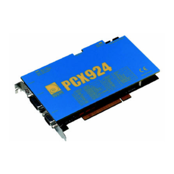
- Page 1 PCX 924 P r o f e s s i o n a l A u d i o C a r d User’s Manual...
- Page 2 Digigram. The copyright protection claimed here includes photocopying, translation and/or reformatting of the information contained in this manual. Digigram is not responsible for errors and omissions and reserves the right to make improvements or changes without prior notice. Digigram and Xtrack are registered trademarks of Digigram. PCXpocket, PCXtools and PCX Designer Kit are trademarks of Digigram.
-
Page 3: Information For The User
PCX 924 User’s Manual INFORMATION FOR THE USER This device complies with part 15 of FCC rules. Operation is subject to the following two conditions: (1) This device may not cause harmful interference, and (2) This device must accept any interference received, including interference that may cause undesired operation. -
Page 4: Hardware Installation
· One LTCinput. Hardware requirements · One card slot, PCI 2.1 compliant. · One available IRQ line. Software requirements · Digigram npRuntime version 5.31 or higher (includes Wave driver). Available options · Analog breakout cable · Digital breakout cable HARDWARE INSTALLATION Installing the card Check for a free PCI expansion slot and gently insert the card. - Page 5 PCX 924 User’s Manual Inter board link cable Boards used in synchronous mode must be connected by an inter-board cable (pin to pin cable). The two switches near the connector must be set on one card in a set of cards linked by an inter-board cable. For one single PCX card, the two switches must be ON.
-
Page 6: Specifications
SPECIFICATIONS Audio inputs Analog line inputs • 2 balanced analog line inputs (can be used with unbalanced signals). • switch selection of maximum input level : +22dBu (Line / +8dBu (CD) • switch selectable input impedance: 600Ohms or >10 kOhms •... - Page 7 PCX 924 User’s Manual Miscellaneous LTC input • Level: -20 dBu min, +6dBu max, speed range: +-10% nominal General Purpose Interface • 2 inputs for dry contact (5VCC / 10mA) do not apply power. • 2 independent contacts, free of power Analog performance •...
-
Page 8: Layout And Connections
LAYOUT AND CONNECTIONS Layout Connectors J1 - Headphone (3.5 mm TRS female jack) Contact Signal sleeve ground left channel ring right channel J2 - Analog Audio connector. (Sub-D 15, female) pin # Signal pin # Signal R Out + R Out – L Out + LOut –... - Page 9 Description Left 2, 3 Ground Right J5 - Interboard sync connector Cable available from Digigram upon request. Switches SW1 - Input impedance (all switches must be set together) Pos. input impedance OFF > 10 kOhm ON 600 Ohm SW2 - Inter board sync switch (all switches must be set together) Pos.
-
Page 10: Schematic Diagram
SCHEMATIC DIAGRAM... - Page 11 PCX 924 User’s Manual NOTES...
- Page 12 Digigram S.A France E-mail : info@digigram.com Digigram Inc. USA E-mail : input@digigram.com Digigram Asia Pte Ltd E-mail : info_asia@digigram.com www.digigram.com DU 143400102 IS=B...
Need help?
Do you have a question about the PCX 924 and is the answer not in the manual?
Questions and answers