Table of Contents
Advertisement
Quick Links
Advertisement
Table of Contents

Related Manuals for Grundfos Hydro 2000 S


Summary of Contents for Grundfos Hydro 2000 S
- Page 1 GRUNDFOS INSTRUCTIONS Hydro 2000 S Installation and operating instructions...
- Page 2 Declaration of Conformity We GRUNDFOS declare under our sole responsibility that the products Hydro 2000 S, to which this declaration relates, are in conformity with the Council Directives on the approximation of the laws of the EEC Member States relating to: —...
-
Page 3: Table Of Contents
Configuration of PCU Relays Product Description Monitoring Functions GRUNDFOS Hydro 2000 S Faults, General GRUNDFOS Control 2000 S Pump- and Motor-Related Faults 2.2.1 Examples of Booster Sets Hydro 2000 S 7.2.1 Communication Faults Functions 7.2.2 Motor Overtemperature Control Functions and Settings Zone-Related Faults 3.1.1... -
Page 5: General
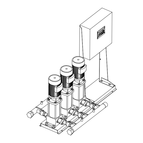
A diaphragm tank must be included in the installation. blocks of flats, hotels, industry, hospitals, schools, etc. Fig. 1 The Hydro 2000 S range includes two types of systems, i.e. MS GRUNDFOS Booster Set Hydro 2000 S and MSH. System... -
Page 6: Grundfos Control 2000 S
2.2 GRUNDFOS Control 2000 S Fig. 2 PFU 2000 Front Cover The GRUNDFOS Control 2000 S controls a number of pumps on mains operation. The Control 2000 S always includes the PFU 2000 with applica- tion-optimized software, but it is also available with a PMU 2000. -
Page 7: Examples Of Booster Sets Hydro 2000 S
2.2.1 Examples of Booster Sets Hydro 2000 S Example: Example: GRUNDFOS Hydro 2000 MS. GRUNDFOS Hydro 2000 MSH. Four pumps and a diaphragm tank. One half-size pump, three full-size pumps and a diaphragm tank. PFU 2000 PFU 2000 One pump in operation. -
Page 8: Functions
Operation with PFU 2000 EPROM settings or PFU 2000 RAM settings can be changed by means of the DIP switches in the PFU 2000. 1. Connect the GRUNDFOS BUS between the PMU 2000 and the PFU 2000. The PFU 2000 EPROM default settings and the PFU 2000 RAM settings are listed in the “List of Control Parameters”. -
Page 9: Closed-Loop Control
The pumps are cut in if the actual value remains below the set- PMU 2000 point. With the “control function” (display 214) set to “normal”, the GRUNDFOS BUS switching-off levels for the cascade-controlled pumps are calcu- lated as follows: PFU 2000... -
Page 10: Manual On/Off And Setting To Max. Or Local
3.1.5 Manual On/Off and Setting to Max. or Local 3.1.6 Water Shortage Monitoring Operation with PFU 2000 RAM / PMU 2000 Settings: The water shortage monitoring function switches off all pumps. Fig. 10 Note: If the booster set has been delivered without a water short- age monitor, it should not be started until a water shortage moni- tor has been installed. -
Page 11: Automatic Pump Change
3.1.7 Automatic Pump Change 3.1.9 Clock Functions There are three possibilities of automatic pump change: Operation with PFU 2000 RAM / PMU 2000 Settings: If the system demand varies during the day and/or during the 1. Operation-dependent pump change. week, the pump performance required will also vary. In this case, This applies to pumps of equal priority. -
Page 12: Reduced Operation
Different settings will be ignored. nected via a GRUNDFOS BUS, the numbering of the pumps, i.e. The default setting is 1. from 1 to 8, must be made on the GRUNDFOS BUS level. Operation with PFU 2000 EPROM Settings: Zone A... -
Page 13: Control Parameters
DIP switches in the PFU Stop 2000 and will be applied by the PMU 2000. Max. If several units are connected via the GRUNDFOS BUS, the GRUNDFOS BUS protocol must be observed. Stop For further information, see sections 3.1.13 GRUNDFOS BUS and... -
Page 14: Setpoint Influences
3.2.4 Setpoint 3.2.5 Setpoint Influences Operation with PFU 2000 RAM / PMU 2000 Settings: Operation with PFU 2000 RAM / PMU 2000 Settings: The maximum setpoint is set in “setpoint max.” (display 200). In order to optimize the operation of the system, it is often advan- This value is the upper limit of the setpoint and forms the basis of tageous to operate the system with a variable setpoint instead of the calculation of “setpoint act.”... -
Page 15: On/Off Band
Remote Control of Setpoint via a PCU 2000: Via PCU 2000 inputs for the pumps connected to the zone and the GRUNDFOS BUS, the setpoint may be controlled linearly to the PCU 2000 input signal. Operation with PFU 2000 EPROM Settings:... -
Page 16: Measuring Unit For Control Value
3.2.7 Measuring Unit for Control Value 3.2.9 Minimum Switching Sequence Operation with PFU 2000 RAM / PMU 2000 Settings: Minimum switching sequence is the time between two switchings (on/off of pumps). If the signal transmitter used features a measuring unit different from the one in the presetting, an alternative measuring unit can Operation with PFU 2000 RAM / PMU 2000 Settings: be selected (display 213). -
Page 17: Control Function
3.2.11 Control Function 3.2.12 PFU 2000 Analog Input 1 Configuration Operation with PFU 2000 RAM / PMU 2000 Settings: The PFU 2000 analog input 1 value is the measured value in the system. The PFU 2000 receives a signal from the signal transmit- The “control function”... -
Page 18: Pfu 2000 Input 4 Configuration
3.2.15 PFU 2000 Input 4 Configuration • “reduced op” (reduced operation) When the PFU 2000 input 4 contact is closed, the pumps The PFU 2000 digital input 4 can be used for external control of which have not been set to reduced operation will be switched the zone. -
Page 19: Minimum Pump Speed Limit
3.2.17 Minimum Pump Speed Limit 3.2.19 Minimum Limit Operation with PFU 2000 RAM / PMU 2000 Settings: Operation with PFU 2000 RAM / PMU 2000 Settings: Minimum pump speed limits the lowest operating point. The value This setting defines the minimum limit at which the system is to is set in the setting menu. -
Page 20: Maximum Head
4.1 Location Operation with PFU 2000 RAM / PMU 2000 Settings: The booster sets Hydro 2000 S must be installed in a well venti- This setting is only possible on service code level. lated room. Hydro 2000 S is not suitable for outdoor installation. -
Page 21: Start-Up
Establish a consumption of approx. 50% of the perform- ance of one pump and await stable operation. 7. If Hydro 2000 S is to be operated without a PMU 2000, it can operate either on the basis of the EPROM settings in the PFU 7. -
Page 22: Taking Out Of Operation
5.4 Taking out of Operation 6. Operation To take the booster set Hydro 2000 S out of operation, switch off the mains switch. 6.1 Operation of PMU 2000 The leads in front of the mains switch are still ener- Fig. 28 gized. -
Page 23: Display Rules
As an example, figure 30 shows the positions of DIPs 1 and 2 and The displays which are not relevant according to the settings and the following settings: the units connected to the GRUNDFOS BUS will be suppressed. • Pump number of the first pump in the zone: 1. -
Page 24: Pfu 2000 Dip Switch Settings
6.2.1 PFU 2000 DIP Switch Settings DIP Switch Setting for PFU 2000: DIP 1 DIP 2 Pump number of the first pump of the PFU 2000: 1 OFF OFF OFF Pump number of the first pump of the PFU 2000: 2 OFF OFF Pump number of the first pump of the PFU 2000: 3 Pump number of the first pump of the PFU 2000: 4... -
Page 25: Configuration Of Pcu Relays
5th - ? time once every 24 hours until the fault has been cor- rected. System time 10 secs. Hydro 2000 S will not restart automatically until the fault has been Minimum switching sequence 10 secs. corrected. Medium switching sequence 120 secs. -
Page 26: Pump- And Motor-Related Faults
(display 228) for more than 0.5 secs., the fault indication “max. “communicat” limit” appears. If a fault occurs in the communication via the GRUNDFOS BUS to With the control parameter “pressure”, this is the overpressure the units connected, the fault indication “communicat” will be gen- fault. -
Page 27: Maintenance
Motors fitted with grease nipples should be lubricated with a high- temperature lithium-based grease, see the instructions on the fan cover of GRUNDFOS motors. In the case of seasonal operation (motor is idle for more than 6 months of the year), it is recommended to grease the motor when the pump is taken out of operation. -
Page 28: Operating And Fault Indications
9. Operating and Fault Indications The two indicator lights (LED) on the front cover of PFU 2000/ PMU 2000 indicate pump operation (green) and/or fault (red). Two external indicator lights (LED) can be connected instead of the two indicator lights (LED) on the front cover. The function of the indicator lights (LED) and the operating and fault signal outputs appears from the table below. -
Page 29: Fault Finding Chart
15 secs. and the fault indication will remain. 3. Unstable water delivery a) Pre-pressure too low. Check the suction pipe and possible suction strainer. from Hydro 2000 S (ap- b) Suction pipe/pumps partly blocked by Clean the suction pipe/pumps. plies only to very low con- impurities. -
Page 30: Technical Data
11. Technical Data 11.1 Hydraulic Data Minimum Pre-Pressure: The minimum pre-pressure “H” in metres head required to avoid cavitation in the pumps is calculated as follows: H = p x 10.2 – NPSH – H – H – H = Barometric pressure in bar. Barometric pressure can be set to 1 bar. -
Page 31: Electrical Data
Number L, N, PE Voltage supply for PFU 2000. 1 x 230-240 V +6% /–10%, 50 Hz, PE. Communication among the units in the GRUNDFOS GRUNDFOS BUS. RS-485, GRUNDFOS BUS proto- A, Y, B Pump Management System 2000. col. -
Page 32: Glossary
PCU 2000 The Pump Communication Unit 2000 is used for communication Analog input between the GRUNDFOS BUS and external control and monitor- Analog signals from transmitters can be connected to the analog ing systems. inputs of PFU 2000 or PCU 2000. -
Page 33: Display Overviews
104 Configuration Zone A alarm suppression 2 tempdif 105 Configuration Zone A pump comm. alarm 3 temp. 106 Configuration Zone A GRUNDFOS 00620194/9420 4 flow 107 Configuration Zone A GRUNDFOS 00610194/9420 5 level 108 Configuration Zone A GRUNDFOS 00630194/9420 6 op.loop. - Page 34 PFU 7: Pressure Setting Menu Set A clock program Set A 12345678 Set A → -> press. setpoint max. 5.0 bar Set A clock program Set A <<< menu >>> on/off 1.0 bar Set A unit Set A setp. influence Set A progressive infl clock program→...
- Page 35 Zone Status Menu Zone Zone Zone A 401 Zone A 402 Zone A setp. influence status status → → press. setpoint act. 5.0 bar setpoint max. 5.0 bar 403 Zone A Zone A setp. influence actual value 0.0 bar remote ->...
- Page 36 PFU 8: Pressure with Pre-Pressure Measuring Setting Menu Set A clock program Set A 12345678 Set A → -> press. setpoint max. 5.0 bar Set A clock program Set A <<< menu >>> on/off 1.0 bar Set A unit Set A setp.
- Page 37 Zone Status Menu Zone Zone Zone A 401 Zone A 402 Zone A setp. influence → → status status press. setpoint act. 5.0 bar setpoint max. 5.0 bar 403 Zone A Zone A setp. influence actual value 0.0 bar remote ->...
- Page 38 Glenmarie Industrial Park Telefax: +66-2-744 1775 ... 6 Finland 40150 Shah Alam OY GRUNDFOS Pumput AB Turkey Selangor GRUNDFOS POMPA SAN. ve TIC. LTD. STI Mestarintie 11 Phone: +60-3-5569 2922 Piispankylä Bulgurlu Caddesi no. 32 Telefax: +60-3-5569 2866 FIN-01730 Vantaa (Helsinki) TR-81190 Üsküdar Istanbul...
- Page 39 Being responsible is our foundation Thinking ahead makes it possible Innovation is the essence 96 40 69 13 1202 Repl. V7 12 16 26 0299...
Need help?
Do you have a question about the Hydro 2000 S and is the answer not in the manual?
Questions and answers