Table of Contents
Advertisement
Advertisement
Table of Contents

Related Manuals for Grundfos Hydro 1000


Summary of Contents for Grundfos Hydro 1000
- Page 1 GRUNDFOS INSTRUCTIONS Hydro 1000 Installation and operating instructions...
-
Page 2: Declaration Of Conformity
Declaration of Conformity We Grundfos declare under our sole responsibility that the products Hydro 1000, to which this dec- laration relates, are in conformity with the Council Directives on the approximation of the laws of the EC Member States relating to: —... -
Page 3: Table Of Contents
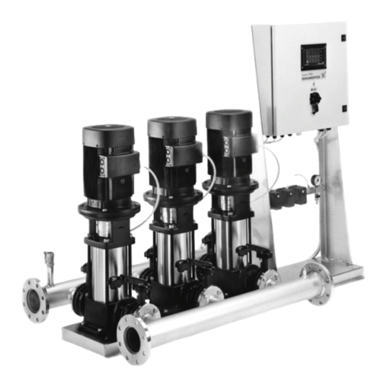
1.1 Applications - potential-free changeover contact for fault indications. Fig. 2 Grundfos booster sets Hydro 1000 are designed for the transfer and pressure boosting of clean water in waterworks, blocks of CS 1000 front cover flats, hotels, industry, hospitals, schools, etc. -
Page 4: Monitoring And Indication Functions
Stop button. When the stop button is pressed, the pump will be taken out of op- eration and the indicator light for automatic Grundfos Hydro 1000 CS maintains an almost constant pres- operation goes out. sure by cutting in/out the required number of pumps. -
Page 5: Installation
4. Installation 4.6 Electrical connection The electrical connection should be carried out by an authorized electrician in accordance with local regulations. 4.1 Location The wiring diagram and motor labels show required values for the The booster set should be placed in a well-ventilated room to en- electricity supply. -
Page 6: Operation Selection
5.2 Operation selection Before changing DIP switch setting, switch off the All operating possibilities for the pumps in your booster set are electricity supply. listed below: Fig. 6 To select operation, proceed as follows: • Switch off the electricity supply to the Control 1000. •... -
Page 7: Alarm Resetting
5.3 Alarm resetting The settings of the pressure switches Pr 2 and Pr 3 are in a de- creasing sequence as shown in the table and fig. 8. There are two possible resetting modes which can be selected by When water is consumed, this is first tapped from the diaphragm means of each of the switches SL and SP. -
Page 8: Start-Up
6. Start-up 7. Maintenance To start up a booster set Hydro 1000, follow this procedure: 7.1 Maintenance of booster set Connect water and electricity supplies. Check that the precharge pressure in the diaphragm tank is See installation and operating instructions for CR pumps. -
Page 9: Fault Finding Chart
8. Fault finding chart Before making any connections in pumps, terminal boxes or control box, the electricity supply must be switched off. Fault Cause Remedy 1. Motor does not run a) Electricity supply disconnected. Connect the electricity supply. when started. b) Automatic circuit breakers cut out. -
Page 10: Parts List
9. Parts list 10.2 Hydraulic data Minimum pre-pressure: Pos. Description Number The minimum pre-pressure “H” in metres head required to avoid cavitation in the pumps is calculated as follows: Suction manifold H = p x 10.2 - NPSH - H Barometric pressure in bar. - Page 11 Telefax: +66-2-744 1775 ... 6 779 00 Olomouc 7 Jalan Peguam U1/25 Turkey Phone: +420-585-716 111 Glenmarie Industrial Park GRUNDFOS POMPA SAN. ve TIC. LTD. STI Telefax: +420-585-438 906 40150 Shah Alam Bulgurlu Caddesi no. 32 Selangor Finland TR-81190 Üsküdar Istanbul...
- Page 12 Being responsible is our foundation Thinking ahead makes it possible Innovation is the essence 96413144 0405 Repl. 96413144 0902 www.grundfos.com...
Need help?
Do you have a question about the Hydro 1000 and is the answer not in the manual?
Questions and answers
Im connecting everything as instructed but im getting this yellow light in the card and im not getting any green light for power what should i do
The provided context does not mention a yellow light or its indication on the Grundfos Hydro 1000 card. However, for resolving the issue of no green power light (which indicates that the electricity supply is connected), the electricity supply should be checked and connected if it is disconnected. If the issue persists, further troubleshooting may be needed.
This answer is automatically generated