Table of Contents
Advertisement
Quick Links
OPERATOR'S MANUAL
Revision #02
5220 Starting Serial #022TS20001
5226 Starting Serial #022TS26009
H&S MANUFACTURING CO.,INC.
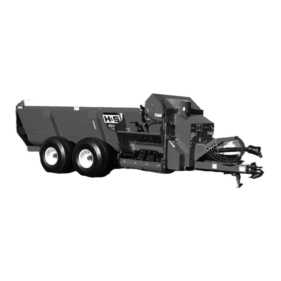
Top Shot
5220/5226
WARNING
Manufactured By
2608 S. HUME AVE. MARSHFIELD, WI 54449
(715) 387-3414 | hsmfgco.com
READ AND UNDERSTAND THIS MANUAL
BEFORE OPERATING THIS EQUIPMENT.
UNSAFE OPERATION OR MAINTENANCE OF
THIS EQUIPMENT CAN RESULT IN SERIOUS
INJURY OR DEATH.
HSMFG0320
Part #73357
Advertisement
Table of Contents

Subscribe to Our Youtube Channel
Related Manuals for H&S 5226


Summary of Contents for H&S 5226
- Page 1 UNSAFE OPERATION OR MAINTENANCE OF WARNING THIS EQUIPMENT CAN RESULT IN SERIOUS INJURY OR DEATH. Revision #02 5220 Starting Serial #022TS20001 5226 Starting Serial #022TS26009 HSMFG0320 Part #73357 Manufactured By H&S MANUFACTURING CO.,INC. 2608 S. HUME AVE. MARSHFIELD, WI 54449...
-
Page 2: Table Of Contents
CONTENTS Warranty ..............1 Manufacturer’s Statement . -
Page 4: Manufacturer's Statement
H&S reserves the right to make changes or add improvements to its products at any time without incurring any obligation to make such changes to products previously manufactured. Specifications, statements and descriptions of Products contained in this publication are subject to change without prior notification. - Page 6 Intentionally Left Blank...
-
Page 7: Dealer Pre-Delivery Checklist
DEALER PRE-DELIVERY CHECKLIST AFTER COMPLETION, DEALER SHOULD REMOVE AND RETAIN FOR RECORDS After the Top Shot has been completely set up, check to be certain it is in correct operating order before delivering to the customer. The following is a list of points to inspect. Check off each item as you have made the proper adjustments and found the item operating satisfactorily. - Page 8 Intentionally Left Blank...
-
Page 9: Dealer Delivery Checklist
DEALER DELIVERY CHECKLIST AFTER COMPLETION, DEALER SHOULD REMOVE AND RETAIN FOR RECORDS This checklist that follows is an important reminder of valuable information that should be passed on to the customer at the time this machine is delivered. Check off each item as you explain it to the customer. This delivery checklist, when properly filled out and signed, assures the customer that the Pre-Delivery Service was satisfactorily performed. - Page 10 Intentionally Left Blank...
-
Page 11: Safety Information - Be Alert Symbol
SAFETY INFORMATION ALERT! YOUR SAFETY IS INVOLVED. THIS SYMBOL IS USED THROUGHOUT THIS BOOK WHENEVER YOUR PERSONAL SAFETY IS INVOLVED. TAKE TIME TO BE CAREFUL. REMEMBER: THE CAREFUL OPERATOR IS THE BEST OPERATOR. MOST ACCIDENTS ARE CAUSED BY HUMAN ERROR. CERTAIN PRECAUTIONS MUST BE OBSERVED TO PREVENT THE POSSIBILITY OF INJURY OR DAMAGE. -
Page 12: Explanation Of Safety Signs
SAFETY INFORMATION Keep signs in good condition. Immediately replace any missing or damaged signs. RECOGNIZE SAFETY INFORMATION This is the safety alert symbol. When you see this symbol on your machine or in this manual, be alert to the potential for personal injury. -
Page 13: Safety Decals
SAFETY INFORMATION... - Page 14 SAFETY INFORMATION -12-...
-
Page 15: Safety Information - Warning - Owner Must Read And Understand
TRACTOR: This Operator’s Manual uses the term “Tractor” when identifying the power source. W A R N I N G TO PREVENT SERIOUS INJURY OR DEATH BEFORE YOU ATTEMPT TO OPERATE THIS EQUIPMENT, READ AND STUDY THE FOLLOWING INFORMATION. IN ADDITION, MAKE SURE THAT EVERY INDIVIDUAL WHO OPERATES OR WORKS WITH THIS EQUIPMENT, WHETHER FAMILY MEMBER OR EMPLOYEE, IS FAMILIAR WITH THESE SAFETY PRECAUTIONS. -
Page 16: Cap Screw Torque Values
-14-... -
Page 17: Set-Up & Assembly
SET-UP & ASSEMBLY WARNING: Some photographs used in the following pages show guards or shields removed for clarification. Never operate machine until these guards or shields are in proper operating position. NOTE: Determine right or left side of the Manure Spreader by viewing it from the rear. If instructions or parts lists call for hardened bolts, refer to the Cap Screw Torque Value page to identify. -
Page 18: Transporting
TRANSPORTING TRANSPORT LIGHTING & REFLECTORS Transport lighting with a 7-pin plug is standard equipment on all Top Shot Models. The lighting system is to be connected to the 7-pin power receptacle (per SAEJ560B) on your tractor. If your tractor is not equipped with the proper receptacle, see your tractor dealer for details. -
Page 19: Preparing For Operation
PREPARING FOR OPERATION PREPARING TOP SHOT Properly lubricate the Top Shot, check automatic oiler level and fill if necessary before operating. Refer to Lubrication Section of this Operator’s Manual for locations. Before loading material, adjust the hitch clevis to your tractor in order to obtain a level or forward position of the Top Shot tank. - Page 20 PREPARING FOR OPERATION TRACTION CONNECTIONS Tractor Hitch 1. The hitch of the Top Shot is designed for a standardized tractor hitch. Adjust the drawbar so that it is 13 to 17 inches above the ground. 2. Extend or shorten it so that the horizontal distance from the end of the tractor power takeoff shaft to the center of the hitch pin hole is 14 inches for 540 RPM PTO and 15-3/4”...
- Page 21 PREPARING FOR OPERATION The Top Shot is equipped with a constant velocity telescoping PTO drive shaft. This constant velocity capability results in a smooth, quiet running drive line without power fluctuation. The Top Shot can only be properly hooked up to a tractor which has PTO and hitch dimensions conforming to ASAE Standard S203.
-
Page 22: Operation
OPERATION EMERGENCY SHUTDOWN In case a foreign object becomes lodged in the expeller or auger area, disengage the PTO. Stop the tractor engine, remove ignition key, and allow all mechanisms to stop before cleaning or working on the machine. If an object is lodged inside the tank, block-up the discharge gate and raise the conveyor auger before attempting to remove the object. - Page 23 OPERATION APPLICATION RATE The side discharge style Top Shot features a hydraulically operated discharge gate to control the material flow out of the tank and into the expeller. Several factors influence the rate of discharge and the spread pattern. These factors include: ground speed, type or consistency of discharge material, PTO RPM, and discharge gate opening.
- Page 24 OPERATION UNLOADING & SPREADING Packed Material To unload and spread packed material and prevent unnecessary stress on the drive line components, observe the following guidelines: 1. Make sure the auger is completely lowered. 2. Engage the tractor PTO at as low an RPM as possible. Then, slowly bring the PTO up to the rated RPM.
- Page 25 6. Expeller Drive Chain Deflection - 1/2”-3/4” ADJUSTABLE EXPELLER SHIELD The 5220 & 5226 Top Shots models have a multi-position manual adjust expeller shield to direct material and provide the best possible performance for delivery of material. An optional hydraulic...
- Page 26 OPERATION CONTROLS & SAFETY EQUIPMENT Top Shots are provided with several features for operator safety and convenience. GUARDS & SHIELDS Whenever possible and without affecting the operation of the Top Shot, guards, shields and/or hinged shields have been used on this equipment to protect potentially hazardous areas. In many places, decals are also provided to warn of potential dangers as well as to display special operation procedures.
- Page 27 OPERATION JACK A jack is furnished with the Top Shot to support the machine when the tractor is disconnected and to adjust the hitch clevis to the tractor drawbar for hookup. The jack should never be used to support a loaded Top Shot. When the jack is not being used to support the Top Shot, it should be relocated to the...
-
Page 28: Adjustments
ADJUSTMENTS DRIVE CHAIN IDLERS Expeller Drive Chain Idler The expeller drive chain is tensioned with an adjustable sprocket Idler. The chain is properly tensioned when the chain can be deflected 1/2” to 3/4” (13-19 mm) with hand pressure. NOTE: If an Idler fails to maintain proper tension, replace the worn chain. - Page 29 ADJUSTMENTS FRONT & REAR AUGER SLIDES The front and rear auger slide assemblies are retained by adjustment plates with diagonal slots. To adjust, loosen retaining hardware and drive the plates downward with a hammer until the slide assembly is snug against the tank, then retighten the retaining hardware.
-
Page 30: Service
SERVICE EXPELLER Periodically inspect the expeller teeth for wear or damage. Damaged, broken, or missing expeller teeth will cause excessive machine vibration. Consult with your local H&S dealer for additional ordering information. AUGER & EXPELLER SPEED OPTIONS The expeller input drive sprocket can be changed by raising the auger and then removing the indicated sprocket which is retained by a snap ring and set screws. - Page 31 19L x 16.1 – 10 Ply 32 PSI 5226 425/65R22.5 85 PSI Wheel bolts must be tightened at 85-95 ft./lbs. of torque on the 5220/5226 STANDARD AXLE. TIRES & WHEELS - HEAVY DUTY AXLE Tire Pressure 21.5L x 16.1 – 18 Ply 425/65R22.5...
-
Page 32: Optional Equipment
The 5220 Top Shot can be ordered from the factory with an optional 1000 RPM drive. 540 RPM PTO DRIVE The 5226 Top Shot can be ordered from the factory with an optional 540 RPM drive. AUGER SPEED OPTIONS Several different drive sprockets are available to change auger speeds to various spreading needs. -
Page 33: Lubrication Guide
LUBRICATION Become familiar with all lubrication points and establish a routine to ensure complete lubrication of the Top Shot. GENERAL INFORMATION IMPORTANT: Catch and dispose of fluid per local waste disposal regulations whenever service is performed on hydraulic components, valves, cylinders, hoses, etc. PTO ASSEMBLY Keep the male and female shafts of the PTO well-lubricated and free-sliding. - Page 34 LUBRICATION DRIVE CHAINS The drive chains are lubricated by a automatic chain oiler. Any time that the discharge door is raised, a specified amount of oil is sent to the brushes on each of the chains. The oiler is adjustable to set the amount that is being discharged.
- Page 35 LUBRICATION GREASING There are numerous grease fittings on the Top Shot. Lubricating properly and often with a high-quality grease will prolong the life of the spreader. Replace any missing or plugged grease fittings. Wipe dirt from the fittings before greasing to prevent the dirt from being forced into the bearing or pivot. Grease should come out around the shaft on sleeve type bearings.
- Page 36 LUBRICATION Grease Fitting Locations - Grease Every 10 Hours (or Daily) Rear Auger Bearing Expeller Bearings (2 Places) Rear Auger Slide Plate (4 Zerks) Expeller Pan Release Pivot Axle Hubs PTO Shaft - As required by Manufacturer Wheel Pivot (Each Side) -34-...
-
Page 37: Decal Location
H&S/Top Shot Decal - Side 71085 H&S/Top Shot Decal - Rear 71068 5220 Model # Decal - Side 71070 5226 Model # Decal - Side 71096 H&S/Top Shot Decal - Front 71090 5220 Model # Decal - Front 71091 5226 Model # Decal - Front... - Page 38 DECAL LOCATION 71068 - (5220) 71064 DCAMB 111209C 71070 - (5226) 093020 DCAMB 093366 71188B 11599 111209C 71085 DCRED DCRED 093020 32320 093020 51010 093020 TFM97 -36-...
- Page 39 DECAL LOCATION 71068 - (5220) 111209C DCAMB 58703 11599 71064 71070 - (5226) 093020 093020 DCAMB 111209B DCRED 11210B 51010 111209B 093020 -37-...
- Page 40 DECAL LOCATION 51010 1494A 11210A 11211176 58703 093020 51010 DCAMB 111209B 1494K 66076 9194A 82602 5896B 102196 1494L 093020 9194A 8515 82602 -38-...
- Page 41 DECAL LOCATION 111209C LW112901 71090 - (5220) 71091 - (5226) 9194B DCAMB 66076 71096 1494B 54033 11599 72203A 1494J 111209A 9194A 11211176 1494A 3494A 1494A 093020 093020 081312 1494A 11599 -39-...
-
Page 42: Troubleshooting Guide
TROUBLESHOOTING NOTE: This Troubleshooting Chapter presents problems, causes and suggested remedies beyond the extent of loose, worn or missing parts and it was developed with the understanding that the machine is in otherwise good operating condition. PROBLEM CAUSE REMEDY 1.) Material NOT Discharge gate is NOT Open gate. -
Page 43: Service Notes
SERVICE NOTES -41-... - Page 44 SERVICE NOTES -41-...
- Page 46 H&S MFG. CO. products approved for the FEMA SEAL OF QUALITY...
Need help?
Do you have a question about the 5226 and is the answer not in the manual?
Questions and answers