Table of Contents
Advertisement
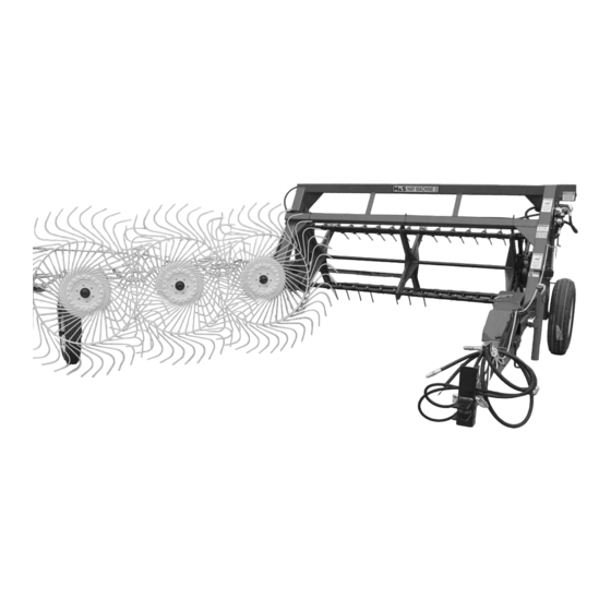
HAYMACHINE II
WARNING
UNSAFE OPERATION OR MAINTENANCE OF THIS EQUIPMENT CAN RESULT IN SERIOUS
INJURY OR DEATH.
OPERATOR'S MANUAL
H&S MANUFACTURING CO., INC.
P.O. BOX 768 • (715) 387-3414 FAX (715) 384-5463
H
&
READ AND UNDERSTAND THIS MANUAL
BEFORE OPERATING THIS EQUIPMENT.
and
PARTS LIST
Manufactured By
MARSHFIELD, WISCONSIN 54449
S
2-28-09
Advertisement
Table of Contents

Related Manuals for H&S HAY MACHINE II


Summary of Contents for H&S HAY MACHINE II
- Page 1 & HAYMACHINE II READ AND UNDERSTAND THIS MANUAL WARNING BEFORE OPERATING THIS EQUIPMENT. UNSAFE OPERATION OR MAINTENANCE OF THIS EQUIPMENT CAN RESULT IN SERIOUS INJURY OR DEATH. OPERATOR’S MANUAL PARTS LIST 2-28-09 Manufactured By H&S MANUFACTURING CO., INC. P.O. BOX 768 • (715) 387-3414 FAX (715) 384-5463 MARSHFIELD, WISCONSIN 54449...
-
Page 2: Table Of Contents
H&S HAYMACHINE II OPERATOR’S AND PARTS MANUAL CONTENTS Warranty & Warranty Registration Card ............1-2 Dealer Pre-Delivery & Delivery Checklist.............3 Be Alert Symbol.....................5 Explanation of Safety Signs ..................6 Danger - Warning Signs ..................7 Warning - Owner Must Read & Understand ............8 Operation - Attaching to Tractor - Loading............9 Adjustments - Beater Control..............10-11-12 Lubrication Guide...................12-13... - Page 3 WARRANTY Mr. Owner: Before Operating–Read and Understand Operating and Safety Instructions H&S Manufacturing Co., Inc. truly believes you have made a wise choice and a sound and lasting investment. Many years of development have made available these quality machines to assure you the performance and reliability you need.
-
Page 4: Dealer Pre-Delivery & Delivery Checklist
IMPORTANT! Tear on dotted line, provide the information requested on the card. The H&S Warranty is valid “only” after this card is received and recorded at H&S Mfg. Co. Mail at once. No postage is required in the U.S.A. This is Your Warranty Card Please Fill Out And Mail Immediately... - Page 5 AFTER COMPLETION, DEALER SHOULD REMOVE AND RETAIN FOR RECORDS H&S DEALER PRE-DELIVERY CHECK LIST After Haymachine II has been completely set-up, check to be certain it is in correct running order before deliver- ing to the customer. The following is a list of points to inspect. Check off each item as you have made the proper adjustments and found the item operating satisfactorily.
-
Page 6: Be Alert Symbol
YOUR SAFETY IS INVOLVED. ALERT! THIS SYMBOL IS USED THROUGHOUT THIS BOOK WHENEVER YOUR PERSONAL SAFETY IS INVOLVED. TAKE TIME TO BE CAREFUL. REMEMBER: THE CAREFUL OPERATOR IS THE BEST OPERATOR. MOST ACCIDENTS ARE CAUSED BY HUMAN ERROR. CERTAIN PRECAUTIONS MUST BE OBSERVED TO PRE- VENT THE POSSIBILITY OF INJURY OR DAMAGE. -
Page 7: Explanation Of Safety Signs
RECOGNIZE SAFETY INFORMATION This is the safety-alert symbol. When you see this symbol on your machine or in this manual, be alert to the potential for personal injury. Follow recommended precautions and safe operating practices. UNDERSTAND SIGNAL WORDS A signal word –DANGER, WARNING, or CAUTION– DANGER is used with the safety-alert symbol. -
Page 9: Warning - Owner Must Read & Understand
H&S HAYMACHINE II W A R N I N G TO PREVENT SERIOUS INJURY OR DEATH BEFORE YOU ATTEMPT TO OPERATE THIS EQUIPMENT, READ AND STUDY THE FOLLOWING INFORMATION. IN ADDITION, MAKE SURE THAT EVERY INDIVIDUAL WHO OPERATES OR WORKS WITH THIS EQUIPMENT, WHETHER FAMILY MEMBER OR EMPLOYEE, IS FAMILIAR WITH THESE SAFETY PRECAUTIONS. -
Page 10: Operation - Attaching To Tractor - Loading
OPERATION 1. Check for proper assembly, and adjustments, and make sure that all bolts and set screws are tightened. Securely retighten after a few hours of operation, as bolts can loosen up on new machinery. Check wheel bolts upon delivery, wheel bolts should be tightened at 55 to 60 ft. lbs. of torque. 2. - Page 11 ADJUSTMENTS While using your H&S Haymachine II, which is capable of turning and tedding quickly and efficiently, you might want to make adjustment changes to make it more efficient. As various conditions will effect the efficiency of your Haymachine II, only with experience will you know how to properly adjust the machine. Field conditions, weather conditions, and type and size of windrow and swath are some of the determining factors for proper teeth adjust- ment, height adjustment, and reel and ground speed to make your Haymachine II most efficient in gently moving, picking up, and fluffing all the hay.
- Page 12 TEDDER REEL SPEED The tedder reel is driven hydraulically to allow the opera- tor to better coordinate the speed of the reel with the ground speed and teeth angle. Adjust reel speed with ground speed so when tedder reel passes over the windrow it gently lifts and fluffs the hay, but does not throw hay into the air.
-
Page 13: Lubrication Guide
Start the tractor and open the rate beam until it contacts the stop. Attempt normal operation of Haymachine II to determine if desired raking angle has been attained. If not, readjust following the same procedure previously described. Top Hole RAKE WHEELS The pressure of the rake wheels on the ground can be changed by changing the position of the spring where it attaches to the rake arm. - Page 14 LUBRICATION (CONTINUED) The operator should become familiar with all lubrication points, and establish a systematic routine to insure com- plete and quick lubrication of the machine. Life expectancy of this or any other machine is dependent on regular maintenance including lubrication, proper adjustment, and bolt torque. GREASE FITTINGS WARNING There are 36 grease fittings on this machine.
-
Page 15: Field Operation
FIELD OPERATION Now that you have properly checked over the H&S Haymachine II, lubricated it, and have it safely attached to the tractor, you are ready to put it into operation. The following steps will aid in proper and most effective operation of the Haymachine. -
Page 16: Optional Equipment
OPTIONAL EQUIPMENT FOURTH RAKE WHEEL Under normal conditions the three rake wheels will turn up to a 4 ’ swath or windrow. If you feel the need to increase raking width, a fourth rake wheel may be added to the rake beam. This extra wheel will allow you to turn up to a six foot swath or windrow. -
Page 17: Decal Location & Identification
DECAL LOCATION Your H&S Haymachine II was manufactured with operator safety in mind. Located on the Haymachine II are vari- ous decals to aid in operation, and warn of danger or caution areas. Pay close attention to all the decals on your Haymachine II. - Page 18 -17-...
-
Page 19: Instructions For Ordering Parts - About Improvements
Instructions for Ordering Parts All service parts should be ordered through your H&S dealer. He will be able to give you faster service if you will provide him with the following. 1. Model number - H&S Haymachine II Serial number - 2. -
Page 20: Service Notes
~ SERVICE NOTES ~ __________________________________________________________________________________________ __________________________________________________________________________________________ __________________________________________________________________________________________ __________________________________________________________________________________________ __________________________________________________________________________________________ __________________________________________________________________________________________ __________________________________________________________________________________________ __________________________________________________________________________________________ __________________________________________________________________________________________ __________________________________________________________________________________________ __________________________________________________________________________________________ __________________________________________________________________________________________ __________________________________________________________________________________________ __________________________________________________________________________________________ __________________________________________________________________________________________ __________________________________________________________________________________________ __________________________________________________________________________________________ __________________________________________________________________________________________ __________________________________________________________________________________________ __________________________________________________________________________________________ __________________________________________________________________________________________ __________________________________________________________________________________________ __________________________________________________________________________________________ __________________________________________________________________________________________ __________________________________________________________________________________________ __________________________________________________________________________________________ __________________________________________________________________________________________ __________________________________________________________________________________________ -19-... - Page 21 FIGURE 1 -20-...
- Page 22 FIGURE 1 MAIN FRAME ASSEMBLY ITEM PART NO. DESCRIPTION BFR129 Hitch Hair Pin BFR5 Hitch Pin T200 Pole T223 Hose Clamp HE42 Hose Clamp BFR319 “I” Bolt T201 Spring T202 Pole Latch Pin T203 Latch Handle T245 Latch Bolt 3/8” X 3” Gr. 5 T204 Pole Pivot Pin T205...
- Page 23 FIGURE 2 -22-...
- Page 24 FIGURE 2 REEL ASSEMBLY ITEM PART NO. DESCRIPTION LH Reel Cross Center Reel Cross RH Reel Cross T784-8 Reel Pipe (8 Hole) T784-9 Reel Pipe (9 Hole) Bronze Bushing 1-1/4” ID (8) Bronze Bushing 1-1/4” ID (4) T116 Nut 5/16” T115 Setscrew for Reel T123...
- Page 25 FIGURE 3 -24-...
- Page 26 FIGURE 3 RAKE BEAM ASSEMBLY ITEM PART NO. DESCRIPTION BFR224 Bolt 1/2” X 4-1/2” Gr. 5 BFR226 Poly Roller Nut 1/2” BFR269 Bronze Washer (1) Full Thread Bolt 3/8” X 3” Gr. 2 BFR267 Brake Pad BFR268 Brake BFR625 Bronze Bushing (2) BFR280A Wheel - Spoked BFR270...
- Page 27 FIGURE 4 -26-...
- Page 28 FIGURE 4 RAKE HYDRAULICS ITEM PART NO. DESCRIPTION T233 Hyd. Hose 3/8” X 168” T234 Hyd. Hose 3/8” X 152” T235 Hyd. Hose 3/8” X 390” T236 Hyd. Hose 3/8” X 378” T237 Hyd. Hose 1/2” X 192” T238 Rope T239 Hyd.
- Page 29 FIGURE 5 FIGURE 5 HYDRAULIC LIFT CYLINDER ITEM PART NO. DESCRIPTION 23N142A Clevis Cap 23N143A Rod Cap 23N144 Piston T184A BFR68 Cyl. Tube T186 Tie Rod 23N148 Piston Nut 23N149 Plug 23N150A Rod Clevis 23N151 Seal Kit BFR69A Complete Cylinder BFR70 Vent Plug -28-...
- Page 30 FIGURE 6 FIGURE 6 HYDRAULIC OPENING CYLINDER ITEM PART NO. DESCRIPTION 23N142A Clevis Cap 23N143A Rod Cap 23N144 Piston 23N145A 23N146 Cyl. Tube 23N147 Tie Rod 23N148 Piston Nut 23N149 Plug 23N150A Rod Clevis 23N151 Seal Kit 12V116A Complete Cylinder T144 Clip Pin T143...
- Page 31 FIGURE 7 -30-...
- Page 32 FIGURE 7 OPTIONAL FOURTH WHEEL ASSEMBLY ITEM PART NO. DESCRIPTION BFR31 RH Rake Wheel BFR229 Steel Washer BFR221 Poly Washer “O” Ring Bushing BFR230 Spacer 3G22 Roll Pin T231 Rake Wheel Arm BFR36 Rake Wheel Spindle BFR138 Spring BFR140 Chain BFR256 Spring Bracket T248...
-
Page 33: Service Notes
~ SERVICE NOTES ~ __________________________________________________________________________________________ __________________________________________________________________________________________ __________________________________________________________________________________________ __________________________________________________________________________________________ __________________________________________________________________________________________ __________________________________________________________________________________________ __________________________________________________________________________________________ __________________________________________________________________________________________ __________________________________________________________________________________________ __________________________________________________________________________________________ __________________________________________________________________________________________ __________________________________________________________________________________________ __________________________________________________________________________________________ __________________________________________________________________________________________ __________________________________________________________________________________________ __________________________________________________________________________________________ __________________________________________________________________________________________ __________________________________________________________________________________________ __________________________________________________________________________________________ __________________________________________________________________________________________ __________________________________________________________________________________________ __________________________________________________________________________________________ __________________________________________________________________________________________ __________________________________________________________________________________________ __________________________________________________________________________________________ __________________________________________________________________________________________ __________________________________________________________________________________________ __________________________________________________________________________________________ -32-... - Page 34 Please do not assume that you know how to operate and main- tain your Haymachine before reading this manual carefully. Keep this manual available for ready reference. H&S HAY MACHINE II SPECIFICATIONS Drive ....................Hydraulic Tedder Reel Drive Transport Wheels ................5 Bolt, 15”x5”...
- Page 35 S MFG. CO. & products approved for the FEMA SEAL OF QUALITY...
Need help?
Do you have a question about the HAY MACHINE II and is the answer not in the manual?
Questions and answers