Table of Contents
Advertisement
Quick Links
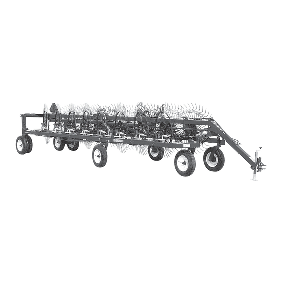
1460 - 1660
HI-CAPACITY RAKE
UNSAFE OPERATION OR MAINTENANCE OF THIS EQUIPMENT CAN RESULT IN
SERIOUS INJURY OR DEATH
OPERATOR'S MANUAL
H&S MANUFACTURING CO.,INC.
P.O. BOX 768 (715) 387-3414 FAX (715) 384-5463
WARNING
AND
PARTS LIST
Manufactured By
MARSHFIELD, WISCONSIN 54449
READ AND UNDERSTAND THIS MANUAL
BEFORE OPERATING THIS EQUIPMENT
HSMFG93008
Advertisement
Table of Contents

Related Manuals for H&S 1460


Summary of Contents for H&S 1460
- Page 1 1460 - 1660 HI-CAPACITY RAKE READ AND UNDERSTAND THIS MANUAL WARNING BEFORE OPERATING THIS EQUIPMENT UNSAFE OPERATION OR MAINTENANCE OF THIS EQUIPMENT CAN RESULT IN SERIOUS INJURY OR DEATH OPERATOR’S MANUAL PARTS LIST HSMFG93008 Manufactured By H&S MANUFACTURING CO.,INC. P.O. BOX 768 (715) 387-3414 FAX (715) 384-5463...
-
Page 2: Table Of Contents
Figure 7 - 1460-1660 Optional 2-Wheel Kicker Wheel....... . .30-31... -
Page 3: Warranty & Warranty Registration Card
WARRANTY H & S WARRANTY H & S Manufacturing Co., Inc. (“H & S”) warrants this product to be free from defect in material and workmanship. Except as noted below, this warranty term is twelve (12) months from the date of delivery of the product to the original purchaser by an authorized H &... - Page 4 IMPORTANT! Tear on dotted line, provide the information requested on the card. The H&S Warranty is valid “only” after this card is received and recorded at H&S Mfg. Co. Mail at once. No postage is required in the U.S.A. NO POSTAGE NECESSARY IF MAILED IN THE...
-
Page 5: Dealer Pre-Delivery & Delivery Checklist
DEALER PRE-DELIVERY CHECK LIST After the 1460-1660 Hi-Capacity Rake has been completely set-up, check to be certain it is in correct operating order before delivering to the customer. The following is a list of points to inspect. Check off each item as you have made the proper adjustments and found the item operating satisfactorily. -
Page 7: Be Alert Symbol
YOUR SAFETY ALERT! IS INVOLVED. THIS SYMBOL IS USED THROUGHOUT THIS BOOK WHENEVER YOUR PERSONAL SAFETY IS INVOLVED. TAKE TIME TO BE CAREFUL. REMEMBER: THE CAREFUL OPERATOR IS THE BEST OPERATOR. MOST ACCIDENTS ARE CAUSED BY HUMAN ERROR. CERTAIN PRECAUTIONS MUST BE OBSERVED TO PREVENT THE POSSIBILITY OF INJURY OR DAMAGE. -
Page 8: Explanation Of Safety Signs
RECOGNIZE SAFETY INFORMATION This is the safety-alert symbol. When you see this symbol on your machine or in this manual, be alert to the potential for personal injury. Follow recommended precautions and safe operating practices. UNDERSTAND SIGNAL WORDS A signal word- DANGER, WARNING, or CAUTION - is used with the safety-alert symbol. -
Page 10: Warning - Owner Must Read And Understand
TRACTORS This operators manual uses the term “Tractor” when identifying the the power source for towing and lifting rake. W A R N I N G TO PREVENT SERIOUS INJURY OR DEATH BEFORE YOU ATTEMPT TO OPERATE THIS EQUIPMENT, READ AND STUDY THE FOLLOWING INFORMATION. -
Page 12: Operation
Re-torque rake tooth bolts after the first 100 acres. (Part No. T175). Check periodically thereafter. NOTE: Determine right or left side of your 1460-1660 Hi-Capacity Rake by viewing it from the rear. If instructions or parts lists call for hardened bolts, refer to bolt torque chart on page 9. - Page 13 OPERATION (Continued) TRANSPORT LOCKS, FRONT & REAR RAKE BEAM LOCKS Transport locks are mounted to the front of the pole. (A) Shows the rake locked into transport position. (B) Shows the transport locks in the convenient storage postion, to be used when in the raking mode. RAKE WHEEL LOCKS Located at the rear of the lift pipe, is a hair pin which is used to secure the rake wheels in the up position for transport (C).
-
Page 14: Adjustments
ADJUSTMENTS HITCH There are ten different positions to adjust the hitch on your new Hi-Capacity Rake. Hitch should be adjusted so main frame of the rake is level or parallel to the ground. GROUND PRESSURE Rake wheel to ground pressure is adjusted by turning Locking Nut and Collar (E) in to decrease pressure, or out to increase pressure. - Page 15 ADJUSTMENTS (Continued) RAKING WIDTH Raking width is determined by setting the spring loaded stop, located above rear pole section as shown. (H) WINDROW WIDTH Windrow width is adjustable from 38” to 58”. Adjustment is made by turning crank (I), located on the left of the rear of the rake as shown.
-
Page 16: Lubrication Guide
GREASE FITTINGS There are 20 grease fittings on the 1460 and 1660 Hi-Capacity Rakes. If equipped with a center kicker wheel, there will be one more on the pivot point. If lubricated properly and often enough, it will prolong the life of your Hi-Capacity Rake. -
Page 17: Decal Location & Identification
DECAL LOCATION Your H&S 1460 and 1660 Hi-Capacity Rake was manufactured with operator safety in mind. Located on the Hi-Capacity Rake are various decals to aid in operation, and warn of danger or caution areas. Pay close attention to all the decals. - Page 18 DECAL LOCATION (Continued) -16-...
-
Page 19: Trouble Shooting
TROUBLE SHOOTING WARNING MAKE SURE THAT THE TRACTOR IS SHUT OFF AND THE RAKE CAN NOT MOVE BEFORE SERVICING THE 1460-1660 HI-CAPACITY RAKE. MAINTENANCE AND REPAIR SERVICE WORK TO BE PERFORMED BY A QUALIFIED SERVICE PERSON ONLY. TROUBLE... POSSIBLE CAUSE... -
Page 20: Optional Equipment
OPTIONAL KICKER WHEEL There are two optional center kicker wheel assemblies available for the 1460-1660 Hi-Capacity Rakes. If the hay is laying out flat, these extra wheels allow you to raise the hay laying in the center of the rake out of the stubble for faster drying, and easier pick-up. -
Page 21: Instructions For Ordering Parts - About Improvements
INSTRUCTIONS FOR ORDERING PARTS All service parts should be ordered through your authorized H & S dealer. They will be able to give you faster service if you will provide them with the following Model & Serial number is located on the left, rear main frame of your unit. All reference to left or right apply to the machine as viewed from the rear. - Page 22 FIGURE 1 -20-...
- Page 23 FIGURE 1 1460-1660 HI-CAPACITY RAKE BEAMS AND LINKAGE ITEM PART NO. DESCRIPTION ITEM PART NO. DESCRIPTION BFR473 Front Rake Beam LH BFR62 Outer Bearing BFR475 Back Rake Beam LH BFR63 Washer BFR472 Front Rake Beam RH BFR65 Cotter Pin BFR474...
- Page 24 FIGURE 2 -22-...
- Page 25 FIGURE 2 1460-1660 HI-CAPACITY RAKE MAIN FRAME ITEM PART NO. DESCRIPTION ITEM PART NO. DESCRIPTION BFR730 Pole BFR65 Cotter Pin BFR714 Center Pole Section BFR144 BFR715 Back Pole Section BFR143 Stud BFR709 Rear Pivot Assembly BFR223 Jack BFR662 Left Axle Upright...
- Page 26 FIGURE 3 -24-...
- Page 27 FIGURE 3 1460-1660 HI-CAPACITY RAKE HYDRAULICS ITEM PART NO. DESCRIPTION 37N60 Hydraulic Hose 108” BFR74 3/8” Female Tee 16SV171A Hydraulic Lift Cylinder (2” x 10”) BFR555 Adapter 3/8” Male To 1/2” Female BFR554 Flow Valve BFR738 Hydraulic Hose 3/8”x255” 1/2”MP x 3/8”MP BFR653 Hydraulic Cylinder (2”...
- Page 28 FIGURE 4 FIGURE 4 1460-1660 HI-CAPACITY RAKE HYDRAULIC LIFT CYLINDER ITEM PART NO. DESCRIPTION 23N142A Clevis Cap 23N143A Rod Cap 23N144 Piston 16SV168A 16SV169 Cylinder Tube 16SV170 Tie Rod 23N148 Piston Nut 23N149 Plug 23N150A Rod Clevis 23N151 Seal Kit 16SV171A Complete Cylinder (2”...
- Page 29 FIGURE 5 FIGURE 5 1460-1660 HI-CAPACITY RAKE HYDRAULIC OPEN CYLINDER ITEM PART NO. DESCRIPTION 23N142A Clevis Cap 23N143A Rod Cap 23N144 Piston BFR 654 BFR655 Cylinder Tube BFR656 Tie Rod 23N148 Piston Nut 23N149 Plug 23N150A Rod Clevis 23N151 Seal Kit BFR653 Complete Cylinder (2”...
- Page 30 FIGURE 6 -28-...
- Page 31 FIGURE 6 1460-1660 HI-CAPACITY RAKE 2-WHEEL EXTENSION KIT ITEM PART NO. DESCRIPTION BFR733 Rake Beam Extension RH BFR534 Pole Extension BFR734 Rake Beam Extension LH BFR537 Lifting Pipe Connector BFR431 LH Spring Clamp BFR430 RH Spring Clamp BFR536 Lifting Pipe Extension...
- Page 32 FIGURE 7 -30-...
- Page 33 FIGURE 7 1460-1660 HI-CAPACITY RAKE OPTIONAL 2-WHEEL KICKER WHEEL ITEM PART NO. DESCRIPTION BFR369 Rake Wheel Ring BFR370 Rake Wheel Center T123 3/8” x 2-1/4” Bolt GR. 5 Rake Wheel Tooth 3/8” Lock Nut BFR371 Rake Wheel Spacer 3/8” Lock Washer...
- Page 34 FIGURE 8 -32-...
- Page 35 FIGURE 8 1460-1660 HI-CAPACITY RAKE OPTIONAL 3-WHEEL KICKER WHEEL ITEM PART NO. DESCRIPTION BFR717 Kicker Rake Beam BFR718 Pivot BFR719 Square Rake Arm BFR514 Kicker Wheel Offset BFR736 Standoff BFR370 Rake Wheel Center BFR369 Rake Wheel Ring Rake Wheel Tooth T123 3/8”...
- Page 36 FIGURE 9 FIGURE 9 1460-1660 HI-CAPACITY RAKE OPTIONAL LIGHTING ITEM PART NO. DESCRIPTION DWM129 Amber Light BFR675 Red Light BFR667 Light Harness (6 Wire) S441 Light Module BFR741 1460 Light Harness BFR706 Front Pig Tail BFR659 Mounting Bracket S317 Tractor Cord (Optional)
-
Page 37: Service And Parts Notes
SERVICE AND PARTS NOTES -35-... -
Page 38: Service Records
SERVICE / MAINTENANCE RECORD DATE DESCRIPTION NOTES -36-... -
Page 39: Specifications
Warranty: See Warranty on Page #1 NOTE: Determine right or left side of 1460-1660 Hi-Capacity Rake by viewing it from the rear. If instructions or parts lists call for hardened bolts see page 9 to identify. H&S MANUFACTURING CO. INC. - Page 40 H&S MFG. CO. products approved for the FEMA SEAL OF QUALITY...
Need help?
Do you have a question about the 1460 and is the answer not in the manual?
Questions and answers