Table of Contents
Advertisement
WARNING:
If the information in these instructions is not followed exactly, a fire or explosion
may result causing property damage, personal injury or loss of life.
•
DO NOT PLACE ARTICLES ON OR AGAINST THIS APPLIANCE.
•
DO NOT USE OR STORE FLAMMABLE MATERIALS NEAR THIS APPLIANCE.
•
DO NOT SPRAY AEROSOLS IN THE VICINITY OF THIS APPLIANCE WHILE IT IS IN OPERATION.
•
DO NOT MODIFY THIS APPLIANCE.
•
Do not store or use gasoline or other flammable vapors and liquids in the vicinity of this or any
other appliance.
WHAT TO DO IF YOU SMELL GAS
• Do not try to light any appliance.
• Do not touch any electrical switch; do not use any phone in your building.
• Immediately call gas supplier from a neighbor's phone. Follow the gas supplier's instructions.
• If you cannot reach your gas supplier, call the fire department.
-
Installation and service must be performed by a qualified installer, service agency or the gas
supplier.
This appliance may be installed in an
aftermarket permanently located,
manufactured home (USA only) or mobile
home, where not prohibited by local codes.
This appliance is only for use with the
type(s) of gas indicated on the rating
plate. A conversion kit is supplied with
the appliance.
Greenfield GSR2 (AU) Manual
INSTALLER:
CONSUMER:
Copyright 2018, T.I.
Leave this manual with the appliance.
Retain this manual for future reference.
$10.00
2/23/2018
• Direct Vent Freestanding Stove
• Natural Gas or Propane
Listed by
AS/NZS 5263.1.3
IAPMO-R&T OCEANA
Dragon Wholesaling Pty. Ltd.
100-01479
GMK10053
Unit 4, 16 Lexington Drive
Bella Vista NSW 2153
Australia
Advertisement
Table of Contents

Subscribe to Our Youtube Channel
Related Manuals for Lopi Greenfield GSR2


Summary of Contents for Lopi Greenfield GSR2
- Page 1 A conversion kit is supplied with the appliance. Dragon Wholesaling Pty. Ltd. Greenfield GSR2 (AU) Manual Unit 4, 16 Lexington Drive INSTALLER: Leave this manual with the appliance. Bella Vista NSW 2153 CONSUMER: Retain this manual for future reference.
-
Page 2: Introduction
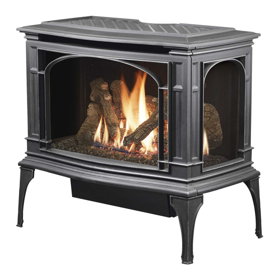
Introduction Introduction We welcome you as a new owner of a Lopi Greenfield GSR2 stove. In purchasing a Greenfield you have joined the growing ranks of concerned individuals whose selection of an energy system reflects both a concern for the environment and aesthetics. The Greenfield is one of the finest home heaters the world over. -
Page 3: Table Of Contents
LP Conversion Instructions ......53 Log Installation ..........29 Index ..............60 Preparing the Burner ........29 Ember Trays ............29 Rear Log Placement ......... 30 Left Log Placement ........... 30 Right Log Placement ........31 © Travis Industries 2/23/18 - 1479 Greenfield GSR2-Aust... - Page 4 Do not operate if any portion of the heater was submerged in water or if any corrosion occurs. Immediately call a qualified service technician to inspect the appliance and to replace any part of the control system and any gas control which has been under water. © Travis Industries 2/23/18 - 1479 Greenfield GSR2-Aust...
- Page 5 Any other statutory regulations • NOT SUITABLE FOR MARINE USE. • NOT INTENDED FOR FIREPLACE INSERT. • APPLIANCES INCORPORATING A LIVE FUEL EFFECT, AND DESIGNED TO OPERATE WITH LUMINOUS FLAMES, MAY EXHIBIT SLIGHT CARBON DEPOSITION. © Travis Industries 2/23/18 - 1479 Greenfield GSR2-Aust...
-
Page 6: Features
This heater is shipped in natural gas (NG) configuration but may be converted to propane (LP) using the included LP conversion kit. The sticker on top of the gas control valve will verify the correct fuel. © Travis Industries 2/23/18 - 1479 Greenfield GSR2-Aust... -
Page 7: Top To Rear Vent Modification
NOTE: If converting to rear vent, you will need the Minimum Vent Kit “D” (sku 96200317) from Travis Industries. This kit includes the necessary rear vent parts and installation instructions. Make sure to review the vent configurations for rear vent before proceeding. © Travis Industries 2/23/18 - 1479 Greenfield GSR2-Aust... -
Page 8: Packing List
Fumes and smoke from the paint curing and oil burning off the steel may occur the first time you start this heater. This is normal. We recommend you open windows to vent the room. © Travis Industries 2/23/18 - 1479 Greenfield GSR2-Aust... -
Page 9: Stove Clearances
(for qualified installers only) Stove Clearances Rear vent installations may not use an elbow with a horizontal termination. We recommend using a top vent configuration if placed in a corner Top to Rear Vent Modification © Travis Industries 2/23/18 - 1479 Greenfield GSR2-Aust... -
Page 10: Heater Placement Requirements
Electrical Requirements • Plug the stove into a grounded receptacle supplying a minimum 1.5 amps (240 Volts). • The appliance, when installed, must be electrically grounded in accordance with local codes. © Travis Industries 2/23/18 - 1479 Greenfield GSR2-Aust... -
Page 11: Gas Line Installation
The supply regulator (the regulator that attaches directly to the residence inlet or to the propane tank) should supply gas at the suggested input pressure listed above. Contact the local gas supplier if the regulator is at an improper pressure. © Travis Industries 2/23/18 - 1479 Greenfield GSR2-Aust... -
Page 12: Vent Requirements
Screws are not required to secure the vent. However, three screws may be used to secure vent sections together if desired. • Horizontal sections require a 1/4" rise every 12" of travel • Horizontal sections require non-combustible support every three feet (e.g.: plumbing tape) © Travis Industries 2/23/18 - 1479 Greenfield GSR2-Aust... -
Page 13: Approved Vent Configurations
NOTE: If the vent configuration calls for restrictor removal, replace the screws into the holes in the firebox ceiling to seal the firebox. © Travis Industries 2/23/18 - 1479 Greenfield GSR2-Aust... - Page 14 The diffuser may be removed from within the firebox and bent into the closed position . This requires removal of the burner, fireback shelf, and rear firebox wall (rivet cover). Once removed, the diffuser may be removed from below, bent 90°, and re-installed. See the illustration below. © Travis Industries 2/23/18 - 1479 Greenfield GSR2-Aust...
- Page 15 Installation (for qualified installers only) Exhaust Restrictor Extender (for rear vent configurations only) • Follow the directions below to install the exhaust restrictor extender. Measuring Vent Lengths © Travis Industries 2/23/18 - 1479 Greenfield GSR2-Aust...
-
Page 16: Rear Vent Configuration With No Rise
Horizontal sections require a ¼” (6mm) rise every 12” (305mm) of travel. • Diffuser must be closed (see page 14). • Exhaust restrictor must be removed. • Do not install the exhaust restrictor extender. © Travis Industries 2/23/18 - 1479 Greenfield GSR2-Aust... -
Page 17: Rear Vent Configuration With Horizontal Termination
NOTE: Restrictor positions are based upon lab tests. The ideal restrictor position may vary slightly, especially when the termination is near a demarcation line. • Diffuser must be closed (see page 14). © Travis Industries 2/23/18 - 1479 Greenfield GSR2-Aust... -
Page 18: Rear Vent Configuration With Vertical Termination
NOTE: Restrictor positions are based upon lab tests. The ideal restrictor position may vary slightly, especially when the termination is near a demarcation line. • Diffuser must be closed (see page 14). © Travis Industries 2/23/18 - 1479 Greenfield GSR2-Aust... -
Page 19: Rear Vent Configuration Vented Into Fireplace With Co-Linear Adapter
Vent height must be a minimum 10’ and maximum 25’. • Exhaust Restrictor must be in Position #3 with the Exhaust Restrictor Extender Installed • Diffuser must be closed (see page 14). © Travis Industries 2/23/18 - 1479 Greenfield GSR2-Aust... -
Page 20: Top Vent Configuration With Vertical Termination
The termination must fall within the shaded area shown in the chart. Use the indicated restrictor and diffuser position. NOTE: Restrictor positions are based upon lab tests. The ideal restrictor position may vary slightly, especially when the termination is near a demarcation line. © Travis Industries 2/23/18 - 1479 Greenfield GSR2-Aust... -
Page 21: Top Vent Configuration With Horizontal Termination
The termination must fall within the shaded area shown in the chart. Use the indicated restrictor and diffuser position. NOTE: Restrictor positions are based upon lab tests. The ideal restrictor position may vary slightly, especially when the termination is near a demarcation line. © Travis Industries 2/23/18 - 1479 Greenfield GSR2-Aust... -
Page 22: Vent Termination Requirements (See Illustration Below)
Minimum 24” (610mm) horizontal clearance to any surface (such as an exterior wall) – for vertical terminations • Use the vinyl siding standoff when installing on an exterior with vinyl siding. • Vent termination must not be located where it will become plugged by snow or other material © Travis Industries 2/23/18 - 1479 Greenfield GSR2-Aust... -
Page 23: Class A Chimney Conversion Kit (Top Vent Configuration Only)
American Metals 8" I.D. Air-Jet 8" I.D. Metal-Fab 8" I.D. American Metals 8" I.D. Each Kit Contains: Retro Connector Retro Vertical Top Additional Required Equipment: 4" Flex (#711 or U.L. 1777) Termination (#991) Co-Axial Sections © Travis Industries 2/23/18 - 1479 Greenfield GSR2-Aust... -
Page 24: Interior Masonry Chimney Conversions (Top Vent Configuration Only)
Minimum vertical rise is 10' (3048mm) • See the chart on page 20 for determining the correct restrictor position. NOTE: these restrictor positions are based upon lab tests. The ideal restrictor position may vary slightly. © Travis Industries 2/23/18 - 1479 Greenfield GSR2-Aust... -
Page 25: Steps For Finalizing The Installation
NOTE: Take care to not touch the bulb with your fingers – use a cloth or paper towel). Install the logs (see page 29). Replace the glass. Start the heater. Leak test all gas joints. © Travis Industries 2/23/18 - 1479 Greenfield GSR2-Aust... -
Page 26: Air Shutter Adjustment
The flames should burn off of each burner hole. If the heater does not work correctly, contact your Travis dealer for a remedy. 12. Give this manual to the home owner for future reference and fully explain operation of this heater. © Travis Industries 2/23/18 - 1479 Greenfield GSR2-Aust... -
Page 27: Face And Glass Removal
If the barrier becomes damaged, the barrier shall be replaced with the manufacturer’s barrier for this appliance (Front Barrier - sku# 250-03375, Side Barrier – sku# 250-03376). The appliance must be completely cool before removing the glass. Do not strike or slam the glass. © Travis Industries 2/23/18 - 1479 Greenfield GSR2-Aust... - Page 28 The latch can come loose from glass frame anchor. This occurs when it is turned 1/4 turn when it is disengaged. Follow the directions below to re-install the latch if it becomes loose. © Travis Industries 2/23/18 - 1479 Greenfield GSR2-Aust...
-
Page 29: Log Installation
The steel ember stands are shipped inside the firebox. Make sure the ember stands are all the way to the back. The ceramic ember trays are shipped with the logs. Place them on top of the ember stands with the flat edges facing inwards. © Travis Industries 2/23/18 - 1479 Greenfield GSR2-Aust... -
Page 30: Rear Log Placement
(see photos below). Position the log so the right side straddles the burner holes. The log must not cover any burner holes and should have a gap at the front (see arrows below). © Travis Industries 2/23/18 - 1479 Greenfield GSR2-Aust... -
Page 31: Right Log Placement
The left twig has a hole in the bottom that fit over a pin on the back log (see photos below). Place the twig as shown below. Note how the front of the twig rests on a flat spot on the left log. © Travis Industries 2/23/18 - 1479 Greenfield GSR2-Aust... -
Page 32: Right Twig Placement
The right twig has one hole in the bottom that fits over a pin on the back log (see photo below). The bottom of the twig rests on both the right and left log. Place the log as shown below. Note how the right twig nearly contacts the left twig. © Travis Industries 2/23/18 - 1479 Greenfield GSR2-Aust... -
Page 33: Front Ember Chunk Placement
Front Ember Chunk Placement Place the ember chunk as shown in the photos below. The left side covers one of the burner screws. Make sure the ember chunk does not cover any burner holes. © Travis Industries 2/23/18 - 1479 Greenfield GSR2-Aust... -
Page 34: Ember Placement
Use a stiff brush to apply a thin layer of rockwool fibers onto the burner. Do not use the entire bag of rockwool. Use only a small amount and save the remainder. Over-use of rockwool will diminish the glow and may cause sooting or other adverse conditions. © Travis Industries 2/23/18 - 1479 Greenfield GSR2-Aust... -
Page 35: Before You Begin
“up” or “down” button to activate or clear the mode being addressed. Make sure to keep the on/off button depressed during this process. Release the on/off button to complete programming. © Travis Industries 2/23/18 - 1479 Greenfield GSR2-Aust... -
Page 36: Remote Set-Up
PRG (Program) button for 10 seconds. The pilot will start to spark repeatedly, signifying all system memory has been cleared. The system will return to its original configuration: a remote will need to be synchronized; and, the system will operate under continuous pilot mode. © Travis Industries 2/23/18 - 1479 Greenfield GSR2-Aust... -
Page 37: Location Of Controls
If you wish to adjust the mode settings use the transmitter mode button to adjust the settings (see “Mode Controls” on page 41). The thermostat and burner on/off operating functions will not work on the transmitter. © Travis Industries 2/23/18 - 1479 Greenfield GSR2-Aust... -
Page 38: Starting The Stove For The First Time
Switching from Intermittent (IPI) to Continuous Pilot (CPI) The pilot mode on this appliance is adjusted using the remote. With the remote in the off position (thermostat off, manual off), follow the directions below to adjust the pilot mode. © Travis Industries 2/23/18 - 1479 Greenfield GSR2-Aust... -
Page 39: Remote Operation
NOTE: When the batteries start to get low, the IFC will beep twice whenever a button is pressed. When the batteries are nearly depleted, the IFC will no longer beep. See “IFC Batteries” on page 43). © Travis Industries 2/23/18 - 1479 Greenfield GSR2-Aust... -
Page 40: Manual On-Off / Smart Thermostat / Standard Thermostat
NOTE: If the transmitter batteries go dead while in thermostat setting (standard or smart), the appliance will shut off after approximately 24 hours. © Travis Industries 2/23/18 - 1479 Greenfield GSR2-Aust... -
Page 41: Mode Controls (Flame, Blower, Light, Comfort Control)
When in Manual Mode the blower will remain on, even if the burner is turned off and the heater cools. Either manually turn the blower off, or turn off the heater by pressing the On/Off button. © Travis Industries 2/23/18 - 1479 Greenfield GSR2-Aust... -
Page 42: Mode Controls - Continued
Comfort Control Mode (see illustration below). The center display will display either “ON” or “OFF”. Display Fahrenheit or Celsius With the system in the “OFF” position, press both the MODE and THERMOSTAT buttons simultaneously to toggle between Fahrenheit (F) and Celsius (C). © Travis Industries 2/23/18 - 1479 Greenfield GSR2-Aust... -
Page 43: Low Battery Indicator
The remote will work if household current (AC power) is disconnected. The batteries inside the battery box will continue to power the heater but the accent light and blower will not operate. © Travis Industries 2/23/18 - 1479 Greenfield GSR2-Aust... -
Page 44: Child-Proof Feature
This appliance has several areas that reach high temperatures. Dust or other particles on these areas may burn and create an odor. This is normal during start-up. You may notice the smell is more acute if the appliance was left idle for a long period. © Travis Industries 2/23/18 - 1479 Greenfield GSR2-Aust... -
Page 45: Maintaining Your Stove's Appearance
The interior of the side glass is cleaned by removing the front glass (page 27) and cleaning the glass from the inside (use soap and water – do not use abrasive cleaners). The exterior of the side glass may be cleaned with compressed air. © Travis Industries 2/23/18 - 1479 Greenfield GSR2-Aust... -
Page 46: Accent Light Replacement
Tighten the screws until the bulb is secure (do not over- tighten, this may damage the electrical contacts on the bulb). When the bulb is inserted into the socket the two posts will be exposed approximately ¼” (6mm) – this is normal. © Travis Industries 2/23/18 - 1479 Greenfield GSR2-Aust... -
Page 47: Yearly Service Procedure
If the pilot or main burners do not burn correctly, contact your dealer for service. Monitor blower operation. 8. Remove any debris or vegetation near the vent termination. Contact your dealer if any sooting or deterioration is found near the vent termination. © Travis Industries 2/23/18 - 1479 Greenfield GSR2-Aust... -
Page 48: Troubleshooting Table
Do Not Work The accent light fuse may be blown..... Replace the fuse. See fuse location below. Location of Fuses The two 3 amp fuses are under the concealment cover (see page 37). © Travis Industries 2/23/18 - 1479 Greenfield GSR2-Aust... -
Page 49: Replacement Parts List
SCREEN BARRIER, SIDE (x1) 250-03376 PILOT ASSY, NG PSE 3-WY 250-02903 PILOT ELECTRODE - PSE 250-02777 VALVE, PROFLAME, NG - GSR 250-01612 Contact your local Dragon Wholesaler Dealer to purchase replacement parts © Travis Industries 2/23/18 - 1479 Greenfield GSR2-Aust... -
Page 50: Wiring Diagram
Maintenance (for qualified service personnel only) Wiring Diagram Caution: Label all wires prior to disconnection when servicing controls. Wiring errors can cause improper and dangerous operation. © Travis Industries 2/23/18 - 1479 Greenfield GSR2-Aust... -
Page 51: Safety Label
Safety Label Safety Label The safety (listing) label is attached under the stove. A copy is shown below. © Travis Industries 2/23/18 - 1479 Greenfield GSR2-Aust... -
Page 52: Conditions & Exclusions
Limited 7 Year Warranty Register your Dragon Wholesaling Limited 7 Year Warranty online at lopi.com.au. Dragon Wholesaling warrants this gas appliance (appliance is defined as the equipment manufactured by Travis Industries, Inc.) to be defect-free in material and workmanship to the original purchaser from the date of purchase as follows: Check with your dealer in advance for any costs to you when arranging a warranty call. -
Page 53: Lp Conversion Instructions
Remove the side ember trays. Grasp the burner with both hands and lift it straight up and out of the firebox. NOTE: When re-installing, make sure the flat edges of the ember trays face inwards. © Travis Industries 2/23/18 - 1479 Greenfield GSR2-Aust... - Page 54 Remove and discard the rear air deflector (see below). Place the LP rear air deflector as shown below. Make sure the round notches fit over the dimples on the burner (see “a” below). Discard the manifold cover (see below). © Travis Industries 2/23/18 - 1479 Greenfield GSR2-Aust...
- Page 55 ORIFICE SIZE (ID) Natural Gas LP (Propane) Front Burner Orifice #49 DMS #57 DMS Rear Burner Orifice #43 DMS #53 DMS Install the LP (propane) manifold cover included in owner’s pack (see illustration below). © Travis Industries 2/23/18 - 1479 Greenfield GSR2-Aust...
- Page 56 (do not over-tighten). Replace the burner, making sure it is correctly seated. Before replacing the ember trays, make sure the steel ember stands are all the way to the back. © Travis Industries 2/23/18 - 1479 Greenfield GSR2-Aust...
- Page 57 Optional Equipment (for qualified installers only) Place the two rivets into the burner holes shown below. 10 Place the included log spacers on the rear log shelves as shown below. © Travis Industries 2/23/18 - 1479 Greenfield GSR2-Aust...
- Page 58 (if applicable), start the heater and thoroughly leak-test all gas connections and the gas control valve. NOTE: See page 29 for information regarding proper operation of the appliance. Test all functions described in the operation section to verify that everything is operating as expected. © Travis Industries 2/23/18 - 1479 Greenfield GSR2-Aust...
- Page 59 Optional Equipment (for qualified installers only) © Travis Industries 2/23/18 - 1479 Greenfield GSR2-Aust...
-
Page 60: Index
Log Installation ..........30 Vent Termination Requirements ...... 23 Wiring Diagram ..........50 Low Battery Indicator ........44 LP Conversion Instructions ......53 Yearly Service Procedure ........ 48 Maintaining Your Stove's Appearance ..... 46 © Travis Industries 2/23/18 - 1479 Greenfield GSR2-Aust...
Need help?
Do you have a question about the Greenfield GSR2 and is the answer not in the manual?
Questions and answers