Table of Contents
Advertisement
SAFETY NOTICE:
If this appliance is not properly installed, a house fire
may result. For your safety, follow the installation
directions. Contact local building or fire officials about
restrictions and installation inspection requirements in
your area.
10850 117th Place N.E. Kirkland, WA 98033
93508131
Copyright 2001, T.I.
4020327
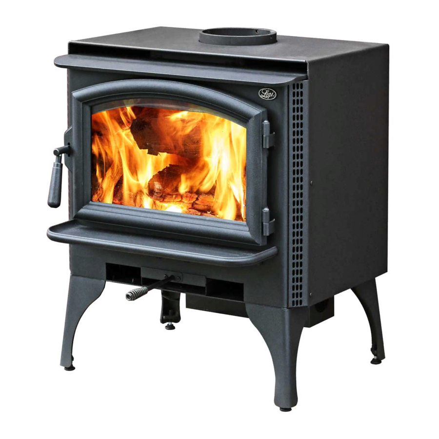
A n s w e r
Wood Stove
Owner's Manual
• Freestanding Stove
• Mobile-Home Approved
• Alcove Approved
• Hearth-Stove Approved
• Masonry Fireplace Insert
• Zero-Clearance (Metal)
Fireplace Insert
$10.00
Tested to: U.L. 1482
Listed
Advertisement
Table of Contents

Related Manuals for Lopi Answer Wood Stove


Summary of Contents for Lopi Answer Wood Stove
-
Page 1: Safety Notice
10850 117th Place N.E. Kirkland, WA 98033 93508131 Copyright 2001, T.I. 4020327 A n s w e r Wood Stove Owner's Manual • Freestanding Stove • Mobile-Home Approved • Alcove Approved • Hearth-Stove Approved • Masonry Fireplace Insert • Zero-Clearance (Metal) Fireplace Insert Listed $10.00... -
Page 2: Introduction & Important Information
Introduction We welcome you as a new owner of a Lopi Answer wood-burning stove. In purchasing a Lopi Answer you have joined the growing ranks of concerned individuals whose selection of an energy system reflects both a concern for the environment and aesthetics. The Lopi Answer is one of the finest appliances the world over. -
Page 3: Table Of Contents
Standard Ceiling with a Factory Built Chimney...14 Cathedral Ceiling with a Factory Built Chimney...14 Exterior Factory Built Chimney ...15 Hearth Stove Positive Connection...15 Hearth Stove Direct Connection ...16 Interior Masonry Chimney ...16 Insert Installation Planning The Installation ...17 Insert Size Requirements...18 Insert Placement Requirements ...18... -
Page 4: Safety Precautions
• • • • • • • Travis Industries Safety Precautions The viewing door must be closed and latched during operation. Never block free airflow through the air vents on this appliance. This appliance is designed and approved for the burning of cord wood only. - Page 5 Safety Precautions • When installed in a mobile home, this appliance must be bolted to the floor, have outside air, and not be Mobile installed in the bedroom (Per H.U.D. requirements). Home Check with local building officials. • Never try to repair or replace any part of this appliance unless instructions are given in this manual.
-
Page 6: Features & Specifications
Note: Measure side, corner, and back clearances from the stove top. The flue collar protrudes 3/4" above the stove top Insert Dimensions: Depth into Fireplace** ...13-1/2" Onto Hearth*** ...3" * For inserts, add 3/4" for the flue collar. ** ZC (metal) fireplaces requre 14-1/2". -
Page 7: Stove Installation
Preparation for Installation • Check for damage to the exterior of the stove (dents should be reported, scratches can be fixed by applying touch up paint). • Check the interior of the firebox (replace cracked firebrick and make sure baffle is in place). -
Page 8: Floor Protection Requirements
Stove Installation Floor Protection Requirements • Stove must be placed on the Travis Industries legs or Pedestal. • Must be non-combustible and at least .018" thick (26 gauge) Floor protection must be non-combustible and at least .018" thick (26 gauge). -
Page 9: Stove Placement Requirements
Stove must be placed so that no combustibles are within, or can swing within (e.g. drapes, doors), 36" of the front of the stove • If the stove is placed in a location where the ceiling height is less than 7', it must follow the requirements in the section "Alcove Installation Requirements" •... -
Page 10: Chimney Requirements
Offsets must be used to maintain the stove to wall clearance. Mobile homes must use the clearances listed in this manual under "Additional Requirements for Mobile Home Installations". -
Page 11: Chimney Termination Requirements
When using outside air, find a location where the chimney and outside air hole do not interfere with structural members of the home. Pedestal (with insulation) directs air to the stove. Air may be drawn from a ventilated crawl space or use an air duct. -
Page 12: Minimum Clearance
Stove Installation Alcove Installation Requirements Whenever the stove is placed in a location where the ceiling height is less than 7' tall, it is considered an alcove installation. Because of the reduced height, the special installation requirements listed below must be met. -
Page 13: Mobile Home Requirements
NOTE: Reduced clearance connectors may not connect to the flue collar – order an appliance adapter for the connector being used. • Stove placement must maintain the following clearances to combustibles (drywall, furniture, etc.) Minimum Clearance (See the illustration below) -
Page 14: Installation Diagrams Standard Ceiling With A Factory Built Chimney
(some require a radiation shield). Minimum Air Space to Combustibles (See Chimney Manufacturer's Instructions - usually 2") Stove Clearances (See the section "Stove Placement Requirements" for more details) Follow the chimney manufacturer's instructions and clearances for roof penetrations. A storm... -
Page 15: Exterior Factory Built Chimney
"Floor Protection support. Requirements" for more details) Travis Industries (for qualified installers only) Wall Bands Supports Stove Clearances (See the section "Stove Placement Requirements" for more details) Min. 18" 93508131 Follow the chimney manufacturer's instructions and clearances for roof penetrations. A storm... -
Page 16: Hearth Stove Direct Connection
Damage must be repaired This type of prior to installation. The chimney installation must be 15' to 33' tall. requires a UBC approved See the section "Stove masonry Placement Requirements" for connector or a minimum clearances required. factory built (U.L. Listed) wall Chimney connector sections thimble. -
Page 17: Insert Installation
Planning The Installation We suggest that you have an authorized Travis Industries dealer install your stove. If you install the stove yourself, your authorized dealer should review your plans for installation. Check with local building officials for any permits required for installation of this stove and notify your insurance company before proceeding with installation. -
Page 18: Insert Size Requirements
Insert Installation Insert Size Requirements (see Illustration below) Insert Placement Requirements • The insert must be placed so that no combustibles are within, or can swing within (e.g. drapes, doors), 36" of the front of the insert • Insert and hearth must be installed on a level, secure floor •... -
Page 19: Masonry Fireplace Requirements
Insert Installation Masonry Fireplace Requirements • Chimney must have a clay tile liner or a stainless steel liner (positive connection) • Entire fireplace, including chimney, must be clean and undamaged. Any damage must be repaired prior to installation of the insert •... -
Page 20: Block-Off Plate Installation
Insert Installation Block-Off Plate Installation Whenever this appliance is installed with a direct connection a block-off plate, or other non- combustible seal-off device (e.g. damper adapter), will need to be installed. This device is used to seal the chimney, insuring no smoke enters the home and providing the chimney system with a seal to promote draft. -
Page 21: Insert With Positive Connection
Insert Installation Insert with Positive Connection NOTE: This installation may be used with a masonry or zero clearance fireplace. The N O T E : requirements in the section Most factory-built "Masonry Fireplace Requirements" chimney or "Zero Clearance Fireplaace manufacturers Requirements"... -
Page 22: Insert With Direct Connection (Zc Fireplace)
Insert Installation Insert with Direct Connection ( Z . C . Fireplace) N O T E : Direct connections require installation of an airtight block-off plate or damper adapter (see "Block-off Plate Installation" on page 20). NOTE: This installation may be used with a masonry fireplace Insert with only. -
Page 23: Operating Your Appliance
If the stove top or other area starts to glow red, you are over-firing the stove. Shut the air control down to low and allow the stove to cool before proceeding. -
Page 24: Starting A Fire
N e v e r use gasoline, gasoline-type lantern fuel, kerosene, charcoal lighter fluid, or similar liquids to start or "freshen up" a fire in this stove. Keep all such liquids well away from the stove while it is in use. -
Page 25: Adjusting The Burn Rate
Operating Your Appliance Adjusting the Burn Rate Use the air control slider to control the burn rate of the stove. See the illustration below for details. Use the air control to change the burn rate. Low Burn High Burn (air control closed) -
Page 26: Optional Blower Operation
Load as much wood as possible. Use large pieces if possible. Let the stove burn on high for 15 minutes to keep the stove hot, then turn the air control to low. In the morning the stove should still be hot, with embers in the coal bed. Stir the coals and load small pieces of wood to re-ignite the fire, if desired. -
Page 27: Hints For Burning
Operating Your Appliance Hints for Burning • Get the appliance hot before adjusting to low burn • Use smaller pieces of wood during start-up and high burns to increase temperature • Use larger pieces of wood for overnight or sustained burns •... -
Page 28: Troubleshooting
• Stove is Not Up to Temperature - This is normal. The blower will come on when the stove is hot - usually 15 to 30 minutes. • Electricity is Cut to the Blower - Check the household breaker or fuse to make sure it is operable. -
Page 29: Maintaining Your Appliance
Generally, remove ash once it has built up over 1". Follow the directions below to remove ash. Let the stove cool completely (at least two hours after the last coal has extinguished). Place a cloth or cardboard protector over the hearth to catch ash and protect against scratching. -
Page 30: Monthly Maintenance
- see “Replacement Parts” for details. The door latch should pull the door against the face of the stove (but not so tight as to not allow full handle rotation). If the latch requires adjustment, follow the directions below. -
Page 31: Yearly Maintenance
Make sure the appliance has fully cooled prior to conducting service. Touch Up Paint Included with the owner's pack of this appliance is a can of Stove-Brite® paint. To touch up nicks or dulled paint, apply the paint while the appliance is cool. -
Page 32: Door Parts
Replacing the Door Gasket The door gasket inserts into the outer groove of the door retainer. Stove gasket cement holds it in place. Before installing, remove any residual cement. Lay the gasket in place (start at the lower left corner) and cut off any excess gasket (do not stretch the gasket. -
Page 33: Firebox Parts
Maintaining Your Appliance Firebox Parts ID # Description Q t y Baffle Support "S" Bar Air Tube Push Pins Brick - 9" x 4.5" un-cut Brick - 9" x 1.375" Floor and Side Firebrick Removal & Replacement Do not pry firebrick - they chip and crack easily. Remove the floor firebricks first. The side firebrick are removed later because they are pinned in place by the floor firebrick. -
Page 34: Baffle Removal And Replacement
Maintaining Your Applia nce Air Tube Removal & Replacement All three air tubes are identical. Air Tube Collar Air Tube Baffle Removal & Replacement The baffle is held up by the front air tube. Make sure to support the baffle after removing the air tubes. Lift the four baffle firebricks then lift the baffle deflector up and over its resting postion. -
Page 35: Warranty
To register your TRAVIS INDUSTRIES, INC. 7 Year Warranty, complete the enclosed warranty card and mail it within ten (10) days of the appliance purchase date to: TRAVIS INDUSTRIES, INC., 10850 117th Place N.E., Kirkland, Washington 98033. TRAVIS INDUSTRIES, INC. warrants this appliance (appliance is defined as the equipment manufactured by Travis Industries, Inc.) to be defect-free in material and workmanship to the original purchaser from the date of purchase as follows: Years 1 &... -
Page 36: Listing Label
Listing Label Travis Industries 93508131 4 020327... -
Page 37: Optional Equipment
1. Determine the location of the outside air hole penetrating the floor (& hearth). The illustration above details the size of pedestal and its location in relation to the stove. The hole may be cut anywhere underneath the pedestal, as long as it is not within 2" of the outside perimeter of the pedestal, is at least 16 square inches in area, and does not interfere with structural members of the home. - Page 38 2. Lift the stove and place a piece of wood along one side to keep it elevated. Use a screwdriver to pry out the forward knock-out underneath the stove (it is 4" wide and 2" deep). 3. Attach the stove to the pedestal with the included bolts. Tuck the included insulation underneath the side edges of pedestal to seal off any air from entering underneath the pedestal.
-
Page 39: Rear Blower Installation
Operating instructions are described in the section "Blower Operation" on page Error! Bookmark not defined.. The stove should be in place with the legs installed prior to installing the rear blower. Follow the directions below to install the thermodisk. These wires pass through the left side convection channel. -
Page 40: Outside Air Boot Installation
Outside Air Boot Installation The outside air boot routes outside air to the stove for combustion. Refer to the section "Outside Air Requirements" on page Error! Bookmark not defined. for installation concerns. The directions below detail installation. Install the cover plate following the directions below (use the cover plate that is 6-1/2" wide). -
Page 41: Surround Panels
Optional Equipment Surround Panels (see part #'s below) Rectangular Panels: Surround Panel Size 8" 10" Arched Panels (Part # 99300108) INSTALLATION INSTRUCTIONS With the insert 12” from the fireplace, install the side surround panels (see the directions below). Pry the button plugs from both sides of the insert. - Page 42 With the insert drawn 6" from the fireplace, glue the insulation strip included with the surround panel kit to the back of the panels using RTV silicon or stove gasket cement. The insulation should be installed so it overlaps the fireplace opening to form a seal between the panels and the fireplace face.
-
Page 43: Front Blower
Optional Equipment Front Blower (part # 99000128) TO SWITCH THE POWER CORD TO THE LEFT SIDE: Use a pair of pliers to disconnect the strain relief which holds the power cord in place. With the power cord slackened, the molex connectors that attach the power cord to the blower assembly may be disconnected. -
Page 44: Index
Smell (from paint curing) ...23 Smoke Enters Room (Troubleshooting)...28 Sounds (Normal Operating Sounds) ...26 Starting a Fire...24 Stove Does Not Burn Long Enough...26 Stove is Not Hot Enough (Troubleshooting) ...28 Table of Contents ...3 Touch-Up Paint...31 Troubleshooting (Operation) ...28 Warranty Card ...2 Warranty...35...
Need help?
Do you have a question about the Answer Wood Stove and is the answer not in the manual?
Questions and answers
Can i burn duralogs in my steel wood stove insert
The provided context does not contain information on whether duralogs can be burned in a Lopi Answer Wood Stove. Check the owner's manual or consult the manufacturer for guidance.
This answer is automatically generated
Why does my lopi blower go on and off during operation
The Lopi Answer Wood Stove blower turns on and off during operation to regulate heat output and maintain proper temperature. This is a normal function of the blower as it pushes air through the stove to distribute heat effectively.
This answer is automatically generated