Table of Contents
Advertisement
Featuring the
WARNING:
If the information in these instructions is not followed exactly, a fire or
explosion may result causing property damage, personal injury or loss of
life.
-
Do not store or use gasoline or other flammable vapors and liquids in the vicinity of this
or any other appliance.
WHAT TO DO IF YOU SMELL GAS
• Do not try to light any appliance.
• Do not touch any electrical switch; do not use any phone in your building.
• Immediately call gas supplier from a neighbor's phone. Follow the gas supplier's
instructions.
• If you cannot reach your gas supplier, call the fire department.
-
Installation and service must be performed by a qualified installer, service agency or the
gas supplier.
This appliance may be installed in an
aftermarket permanently located,
manufactured home (USA only) or mobile
home, where not prohibited by local
codes.
This appliance is only for use with the
type(s) of gas indicated on the rating plate.
A conversion kit is supplied with the
appliance.
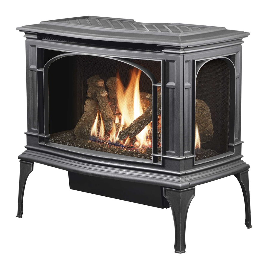
GreenField
INSTALLER:
Leave this manual with the appliance.
CONSUMER:
Retain this manual for future reference.
© Copyright 2010, T.I.
Burner
Owner's Manual
$10.00
100-01255_000
• Direct Vent Freestanding Stove
• Natural Gas or Propane
• Vent Horizontally or Vertically
• Standard Residential
• Mobile Home Approved
Tested and Listed by
ANSI Z21.88 CSA 2.33
www.travisproducts.com
4800 Harbour Pointe Blvd. SW
4101028
Mukilteo, WA 98275
Advertisement
Table of Contents

Subscribe to Our Youtube Channel
Related Manuals for Lopi GreenField


Summary of Contents for Lopi GreenField
- Page 1 This appliance is only for use with the type(s) of gas indicated on the rating plate. A conversion kit is supplied with the appliance. GreenField Owner’s Manual INSTALLER: Leave this manual with the appliance. CONSUMER: Retain this manual for future reference.
-
Page 2: Introduction & Important Information
Introduction Introduction We welcome you as a new owner of a Lopi GreenField stove. In purchasing a GreenField you have joined the growing ranks of concerned individuals whose selection of an energy system reflects both a concern for the environment and aesthetics. The GreenField is one of the finest home heaters the world over. -
Page 3: Table Of Contents
Table of Contents Introduction Operation Introduction & Important Information ....2 Before You Begin ..........34 Location of Controls ..........34 Safety Precautions Starting the Stove for the First Time ....35 Safety Precautions ..........4 Turning the Stove On and Off ......35 Features &... -
Page 4: Safety Precautions
Safety Precautions • IF YOU SMELL GAS: * Do not light any appliance * Extinguish any open flame * Do not touch any electrical switch or plug or unplug anything * Open windows and vacate building * Call gas supplier from neighbor's house, if not reached, call fire department •... -
Page 5: Travis Industries
Safety Precautions • Do not place clothing or • Light the heater using the other flammable items on or built-in igniter. Do not use near the heater. Because matches or any other this heater can be controlled external device to light your by a thermostat there is a heater. -
Page 6: Features
Specifications Features: Installation Options: Ember Fyre™ Burner for "Wood Fire" Look Freestanding Stove Works During Power Outages (battery backup system) Horizontal or Vertical Vent High Efficiency Optional Thermostat or Remote Control Residential or Mobile Home Optional Blower for Quicker Heat Distribution Straight or Corner Placement Convenient Operating Controls Variable-Rate Heat Output... -
Page 7: Installation
Installation (for qualified installers only) Installation Warnings: Failure to follow all of the requirements may result in property damage, bodily injury, or even death. This heater must be installed by a qualified installer who has gone through a training program for the installation of direct vent gas appliances. -
Page 8: Packing List
Installation (for qualified installers only) Packing List Additional Items Required • Propane Conversion Kit • Vent (see “Venting Requirements” for details) • Log Set • Gas Line Equipment (shutoff valve, pipe, etc.) • Touch-Up Paint • ½” FPT to 3/8” Flare Fitting •... -
Page 9: Stove Clearances
Installation (for qualified installers only) Stove Clearances Top Vent Top Vent Straight Installations Corner Installations With this clearance the top vent is With this clearance, the vent is centered 6-3/4" (172mm) from the centered 17" (432mm) from back wall, 25-7/8" (658mm) from the wall. - Page 10 Installation (for qualified installers only) Top to Rear Vent Modification NOTE: The rear vent parts are included in the Minimum Vent Kit “D” (sku 96200317). If using the rear vent configuration, make sure to review vent configuration before proceeding. © Travis Industries 4101028 100-01255_000...
-
Page 11: Mobile Home Requirements
Installation (for qualified installers only) Heater Placement Requirements • Heater must be installed on a level surface capable of supporting the heater and vent • Due to the high temperature, the heater should be located out of traffic and away from furniture and draperies. -
Page 12: Optional Wall Switch Or Thermostat Installation
Installation (for qualified installers only) Optional Wall Switch or Thermostat Installation Do not connect 110-120 VAC to the gas control valve or wiring system of this stove. The switch must be installed by a qualified installer. This stove may be installed with an optional wall switch or thermostat. The thermostat (or on/off switch) wires will interrupt the burner circuit (see item “a”... -
Page 13: Gas Line Installation
Installation (for qualified installers only) Gas Line Installation The gas line must be installed in accordance with all local codes, if any; if not, follow current ANSI Z223.1 or NFPA 54 in the USA and the current CSA B149.1 in Canada. The heater and gas control valve must be disconnected from the gas supply piping during any pressure testing of that system at test pressures in excess of 1/2 psig (3.45 kPA). -
Page 14: Vent Requirements
Installation (for qualified installers only) Vent Requirements • The gas appliance and vent system must be vented directly to the outside of the building, and never be attached to a chimney serving a separate solid fuel or gas-burning appliance. Each direct vent gas appliance must use it's own separate vent system. -
Page 15: Approved Vent Configurations
Installation (for qualified installers only) Approved Vent Configurations Exhaust Restrictor Position • An exhaust restrictor is built into the appliance to control the flow rate of exhaust gases. This ensures proper flames for the wide variety of vent configurations. Depending upon the vent configuration, you may be required to adjust the restrictor position. -
Page 16: Closing The Diffuser
Installation (for qualified installers only) Closing the Diffuser (stock position is open) -- (for top vent configurations only) IMPORTANT NOTE: The diffuser can be easily closed with no vent in place. Consult the vent configuration charts to determine diffuser position. If the diffuser needs to be in the closed position, adjust the diffuser prior to installing vent. -
Page 17: Exhaust Restrictor Extender
Installation (for qualified installers only) Exhaust Restrictor Extender (for rear vent configurations only) • Follow the directions below to install the exhaust restrictor extender. Remove these two screws on the exhaust restrictor. Exhaust Restrictor Extender Plate (included in the rear vent kits) Use the screws to attach the extender to the exhaust restrictor. -
Page 18: Rear Vent Configuration With No Rise
Installation (for qualified installers only) Rear Vent Configuration with No Rise • Use the minimum vent kit “D” from Travis Industries (SKU 96200317). This kit contains the following components used to vent the stove through a typical exterior wall: -- Travis Thimble (unique to this stove) -- Wall Cover (Black) -- Pipe Section (3.9”) -- Pipe Section (6”) -
Page 19: Rear Vent Configuration With Horizontal Termination
Installation (for qualified installers only) Rear Vent Configuration with Horizontal Termination • Use the rear vent conversion from Travis Industries (SKU 94400998). • Use 8” Diameter Vent • Horizontal sections require a ¼” (6mm) rise every 12” (305mm) of travel. •... -
Page 20: Rear Vent Configuration With Vertical Termination
Installation (for qualified installers only) Rear Vent Configuration with Vertical Termination • Use the rear vent conversion from Travis Industries (SKU 94400998). • Use 8” Diameter Vent • Horizontal sections require a ¼” (6mm) rise every 12” (305mm) of 31' max (9.3m) 31' max (9.3m) travel. -
Page 21: Top Vent With Horizontal Termination
Installation (for qualified installers only) Top Vent Configuration with Vertical Termination • Use 6-5/8” Diameter Vent • Horizontal sections require a ¼” (6mm) rise every 12” (305mm) of travel. • A maximum of four (4) 45° or 90° elbows may be used. Of these elbows, only one (1) may be a horizontal elbow (see illustration). -
Page 22: Top Vent With Vertical Termination
Installation (for qualified installers only) Top Vent Configuration with Horizontal Termination • Use 6-5/8” Diameter Vent • Horizontal sections require a ¼” (6mm) rise every 12” (305mm) of travel. • A maximum of four (4) 45° or 90° elbows may be used. Of these elbows, only one (1) may be a horizontal elbow (see illustration). -
Page 23: Vent Termination Requirements
Installation (for qualified installers only) Vent Termination Requirements (see illustration below) Venting terminals shall not be recessed into a wall or siding. Minimum 9" (229mm) clearance from any door or window Roof Minimum 12" (305mm) above any grade, veranda, porch, deck or balcony Surface Minimum 12"... -
Page 24: Leak Test
Installation (for qualified installers only) Steps for Finalizing the Installation Remove the glass (see page 26). NOTE: If using propane (LP) convert the appliance prior to installing the logs. We recommend you purge the gas line at this time (with the glass removed). This allows gas to be detected once it enters the firebox, ensuring gas does not build up. -
Page 25: Air Shutter Adjustment (If Necessary)
Installation (for qualified installers only) Check the air shutter following the directions below. Air Shutter Adjustment Let the heater burn for fifteen minutes (make sure the logs and glass are in place). The flames should be yellow with no sooting. Adjust the air shutter, if necessary, to achieve the correct looking flame. -
Page 26: Face And Glass Removal
Finalizing the Installation (for qualified installers only) Face and Glass Removal Make sure the gas control valve is “OFF” and the heater is cool prior to conducting service. Open the two latches holding the glass frame in place - follow the directions shown below Lift the stove top off the stove and place it aside. - Page 27 Finalizing the Installation (for qualified installers only) Glass Frame Removal and Installation (continued) The latch can come loose from glass frame anchor. This occurs when it is turned 1/4 turn when it is disengaged. Follow the directions below to re-install the latch if it becomes loose.
-
Page 28: Log Installation
Finalizing the Installation (for qualified installers only) Log Installation The logs are fragile, especially after being exposed to heat. • Make sure the gas control valve is “OFF” and the heater is cool prior to conducting service. • Failure to position the parts in accordance with these diagrams or failure to use only parts specifically approved with this appliance may result in property damage or personal injury. - Page 29 Finalizing the Installation (for qualified installers only) Rear Log Placement The rear log has two obround holes on the bottom. Place the log so the pins on the burner insert into the holes on the log (see photos below). Once in place, carefully pull the log all the way forward. This allows the log to glow above the rear burner holes.
- Page 30 Finalizing the Installation (for qualified installers only) Right Log Placement The right log has a hole on the bottom. Place the log so the bolt on the burner inserts into the hole on the log (see photos below). Make sure the log is pushed back so it sits flat against both sides of the bracket attached to the burner.
- Page 31 Finalizing the Installation (for qualified installers only) Right Twig Placement The right twig has one hole in the bottom that fits over a pin on the back log (see photo below). The bottom of the twig rests on both the right and left log. Place the log as shown below. Note how the right twig nearly contacts the left twig.
- Page 32 Finalizing the Installation (for qualified installers only) Front Ember Chunk Placement Place the ember chunk as shown in the photos below. The left side covers one of the burner screws. Make sure the ember chunk does not cover any burner holes. ©...
- Page 33 Finalizing the Installation (for qualified installers only) Ember Placement Embers are included with your appliance to enhance the firebox. Place embers on top of screw- heads and along the perimeter of the burner and firebox to enhance the aesthetics of the firebox. Do not place embers over any burner holes.
-
Page 34: Before You Begin
Operation Before You Begin Warning: Read this entire manual before you use your new stove (especially the section "Safety Precautions" on pages 4 & 5). Failure to follow the instructions may result in property damage, bodily injury, or even death. Warning: Do not operate appliance with the glass front removed, cracked or broken. -
Page 35: Starting The Stove For The First Time
Operation Starting the Stove for the First Time • Burn the heater at a high setting with the blower off for an extended period (up to 48 hours). This will cure the painted surfaces. Fumes from the paint curing and oil burning off the steel will occur. This is normal. -
Page 36: Accent Light
Operation Accent Light This stove has a built-in accent light HIGH that may be turned on and off and dimmed to your preference. Turn the knob to achieve the desired light output. ACCENT LIGHT Adjusting the Optional Blower Speed The blower helps transfer heat from the heater into the room. It will not turn on until the heater is up to temperature (approximately 15 minutes after starting). -
Page 37: Normal Operating Sounds
Operation Normal Operating Sounds Extinction Pops It is not unusual, especially on Propane The appliance may creak with change of (LP) appliances, to experience a "pop" temperature -- THIS IS NORMAL. when the burner is shut off. Blower Pilot Assembly This heater has an optional blower to push The pilot flame will make a clicking heated air into the room. -
Page 38: Maintenance
Maintenance (for qualified service personnel only) Maintaining Your Stove's Appearance Painted Surfaces • Painted surfaces should be cleaned with a duster. If scratches occur, lightly sand the area with fine sandpaper. Clean the area and, with the stove cool, apply one or two thin coats of stove paint to the area (mask the area to avoid overspray). -
Page 39: Accent Light Replacement
Maintenance (for qualified service personnel only) Accent Light Replacement An accent light is included in your stove to provide additional lighting. To replace the bulb, follow the directions below: • Disconnect stove from power. Shut off gas to the stove. Make sure the stove is cool before proceeding (15 minutes). -
Page 40: Yearly Service Procedure
Maintenance (for qualified service personnel only) Yearly Service Procedure • Failure to inspect and maintain the stove may lead to improper combustion and a potentially dangerous situation. We recommend the following procedures be done by a qualified technician. Turn the pilot flame to continuous. It should touch approximately 3/8" of the top of the flame sensor. If it does not, contact your dealer for service. -
Page 41: Troubleshooting Table
Maintenance (for qualified service personnel only) Troubleshooting Table Problem: Possible Cause: Don't Call for Service Until You: The ON/OFF switch is turned to "OFF" Turn the ON/OFF switch to "ON" Main Burners Will The remote control is not working correctly See the remote control instructions Not Start The thermostat is disconnected or set too low... -
Page 42: Wiring Diagram
Maintenance (for qualified service personnel only) Wiring Diagram Caution: Label all wires prior to disconnection when servicing controls. Wiring errors can cause improper and dangerous operation. Verify proper operation after servicing. Spark Rod Accent Pilot Light (s) Sensor Accent Light Rheostat Pilot Ground Optional... -
Page 43: Replacement Parts List
Maintenance (for qualified service personnel only) Replacement Parts List Caution: Use only Travis Industries replacement parts. Do not use substitute materials. Warning: Do not operate appliance with the glass front removed, cracked, or broken. Replacement of the glass should be done by a licensed or qualified service person. -
Page 44: Safety Label
Safety Label Safety Label The safety (listing) label is attached under the stove. A copy is shown below. © Travis Industries 4101028 100-01255_000... -
Page 45: Warranty
Limited Lifetime Warranty Register your TRAVIS INDUSTRIES, INC. Limited 7 Year Warranty online at traviswarranty.com, or complete the enclosed Warranty card and mail it within ten (10) days of the appliance purchase date to: TRAVIS INDUSTRIES, INC., 4800 Harbour Pointe Blvd. SW, Mukilteo, WA 98275. TRAVIS INDUSTRIES, INC. warrants this gas appliance (appliance is defined as the equipment manufactured by Travis Industries, Inc.) to be defect-free in material and workmanship to the original purchaser from the date of purchase as follows: Check with your dealer in advance for any costs to you when arranging a warranty call. -
Page 46: Optional Equipment
Optional Equipment (for qualified installers only) LP Conversion Instructions WARNING This conversion kit shall be installed by a qualified service agency in accordance with the manufacturer’s instructions and all applicable codes and requirements of the authority having jurisdiction. If the information in these instructions are not followed exactly, a fire, explosion or production of carbon monoxide may result causing property damage, personal injury or loss of life. - Page 47 Optional Equipment (for qualified installers only) 3 Remove and discard the rear air deflector (see below). Place the LP rear air deflector as shown below. Make sure the round notches fit over the dimples on the burner (see “a” below). 4 Discard the manifold cover (see below).
- Page 48 Optional Equipment (for qualified installers only) 5 Install the LP (propane) orifices. Rear Burner Orifice Front Burner Orifice Thread Sealant 15/16" 24mm 1/2" Wrench Orifice ID ORIFICE SIZE (ID) Natural Gas LP (Propane) Front Burner Orifice #49 DMS #57 DMS Rear Burner Orifice #43 DMS #53 DMS...
- Page 49 Optional Equipment (for qualified installers only) 6 Install the LP (propane) manifold cover included in owner’s pack (see illustration below). 7 Remove the pilot orifice following the instructions below. Replace with the propane pilot orifice. Remove the orifice and replace with the LP orifice. Screw the Lift the pilot hood orifice all the way in and replace the pilot hood.
- Page 50 Optional Equipment (for qualified installers only) 9 Place the two rivets into the burner holes shown below. Back of Burner Front of Burner 10 Place the included log spacers on the rear log shelves as shown below. © Travis Industries 4101028 100-01255_000...
- Page 51 Optional Equipment (for qualified installers only) 11 Replace the regulator following the instructions included with the regulator kit. Remove and discard the screws (see “a” below) holding the stock regulator in place (see “b” below). Remove the stock regulator and gasket (see “c” below). Place the LP regulator in place, making sure the pre-fitted gasket (see”c”...
-
Page 52: Greensmart™ Remote Control Installation
Optional Equipment (for qualified installers only) GreenSmart™ Remote Control Installation Packing List • Transmitter • Receiver (with Cover Plate & Switch) • Fan Control Module • Velcro • LP or NG Stepper Motor (with screws and label - attaches to Valve) •... - Page 53 Optional Equipment (for qualified installers only) Overview The GreenSmart remote includes a new wiring harness that replaces the stock wiring harness. Before installing, familiarize yourself with the stock and updated wiring diagrams (see the illustrations on this page and and following page). Stock Wiring Diagram Spark Rod Accent...
- Page 54 Optional Equipment (for qualified installers only) GreenSmart Wiring Diagram Spark Rod Pilot Comfort Control Sensor Valve PILOT DIGITAL SENSOR FIREPLACE BURNER CONTROL SPARK ROD DIAGNOSTIC Pilot VALVE COMMAND POWER Ground GROUND BURNER CONTROL RECEIVER Orange Green Remote Yellow / Green Receiver IPI / CPI Blue...
- Page 55 Optional Equipment (for qualified installers only) Installation WARNING: Make sure power to the stove has been shut off prior to installation. NOTE: Refer to the wiring diagram on page 54 while making wiring harness connections. Loosen the bottom panel attachment screws (there are two on each side see Figure 1). Slide the bottom panel back and place it below the stove (see Figure 2).
- Page 56 Optional Equipment (for qualified installers only) Unplug the ac adapter from the power harness (see Figure 5). You can leave the ac adapter plugged into the wiring harness. Figure 5 Disconnect the molex connector leading to the gas control valve (see Figure 6). WARNING: The tabs on the gas control valve are fragile.
- Page 57 Optional Equipment (for qualified installers only) Disconnect the comfort control valve connection (see Figure 8). Disconnect the burner control connector from the fireplace burner control (see Figure 9). Figure 8 Figure 9 Disconnect the on/off switch wires (labeled ON/OFF - see Figure 10). Unscrew the on/off/battery plate from the control panel (see Figure 11).
- Page 58 Optional Equipment (for qualified installers only) Use the included torx wrench to remove the stock regulator (see Figure 14). The old regulator may be discarded. Figure 14 10 The stepper motor (adjustable regulator) has an installation sheet included with it – make sure to follow all of the directions.
- Page 59 Optional Equipment (for qualified installers only) 12 Attach the wiring harness to the burner control (see Figure 18). Attach the gas control valve molex connector (see Figure 19). Figure 18 Figure 19 13 Attach the blue and white wires to the IPI/CPI switch (see Figure 20). Connect the wiring harness to the stepper motor (see Figure 21).
- Page 60 Optional Equipment (for qualified installers only) 15 Place the fan controller on the bottom panel as shown in Figure 23. Make sure the control module is positioned with the power cord to the right and the module at the back edge of the bottom panel. Figure 23 16 Attach the power cord from the fan controller to the AC connection (see Figure 24).
- Page 61 Optional Equipment (for qualified installers only) 18 Attach the accent light power lead to the fan controller in the “AUX OUT” receptacle (see Figure 28). Figure 28 NOTE: If using the optional fan, you will want to disconnect its power lead and connect it to the extra power lead included with this kit, then connect it to the “FAN”...
- Page 62 Optional Equipment (for qualified installers only) 20 Attach the receiver to the control panel with the two #8 machine screws (Figure 31). Figure 31 21 Re-attach the bottom plate to stove, taking care to prevent any wiring from being pinched (see Figure 32).
- Page 63 Optional Equipment (for qualified installers only) 23 Place the receiver coverplate (and switch) over the receiver (see Figure 35) and attach with the two screws included with the receiver (see Figure 36) Figure 36 Figure 35 24 A wall mount is included with this kit for the remote. It may be mounted to the wall for easy access and storage.
-
Page 64: Index
Index Approved Vent Configurations ......15 Installation Options ..........6 Adjusting the Blower Speed ......... 36 Items Required for Installation ......7 Adjusting the Flame Height ........35 Leaking Gas ....... See Inst. on Cover Air Shutter Adjustment ......... 25 Listing Information ..........
Need help?
Do you have a question about the GreenField and is the answer not in the manual?
Questions and answers
how do I program my remote, I have replaced all the batteries but cannot get it to go on and off with the remote
To program the Lopi GreenField remote control:
1. Power On: Press the power button to turn the remote on.
2. Check Mode: The top left corner of the display shows whether the remote is in manual or remote mode.
3. Set Temperature: Use the top right corner display to check the current temperature setting.
4. Change Modes: Press the middle button to cycle through the available modes.
5. Adjust Settings: Use the up and down arrows to change temperature or other settings.
6. Switch Operation Mode: The receiver can be set to manual or remote operation.
7. Battery Replacement: The receiver unit can be removed easily to replace the batteries.
These steps allow you to control the stove’s settings using the remote.
This answer is automatically generated
I have a Lopi Greenfield GS vented gas fireplace heater manufactured in 2011 40,000 BTU installed in a corner on a 60" corner brick pad which protrudes 10" into a doorway. We would like to get a smaller pad that would clear the doorway and we have received different answers on how much clearance we need for a pad on our laminate floors. How much clearance is necessary from glass sides to walls and also from front of fireplace glass to front edge of pad?