Lopi Endeavor Owner's Manual
Lopi owner's manual wood stove endeavor
Hide thumbs
Also See for Endeavor:
- Owner's manual (38 pages) ,
- Owner's manual (38 pages) ,
- Owner's manual (34 pages)
Table of Contents
Advertisement
SAFETY NOTICE:
If this appliance is not properly installed, a house fire may
result. For your safety, follow the installation directions.
Contact local building or fire officials about restrictions and
installation inspection requirements in your area.
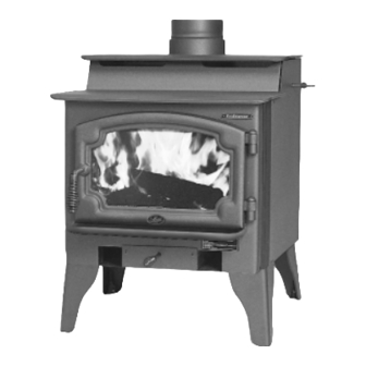
Wood Stove
Copyright 2007, T.I.
$10.00
100-01161
4050923
E n d e a v o r
Owner's Manual
Freestanding Stove
Mobile-Home Approved
Alcove Approved
Hearth-Stove Approved
Save these instructions
for future reference
Tested to: U.L. 1482
Listed
Advertisement
Table of Contents

Related Manuals for Lopi Endeavor


Summary of Contents for Lopi Endeavor
-
Page 1: Safety Notice
For your safety, follow the installation directions. Contact local building or fire officials about restrictions and installation inspection requirements in your area. E n d e a v o r Wood Stove Owner's Manual Freestanding Stove Mobile-Home Approved Alcove Approved... - Page 2 Introduction Important Information Introduction Mail your Warranty Card Today, and Save Your Bill of Sale.
- Page 3 General Information Stove Installation INSTALLATION DIAGRAMS Operating Your Appliance Table of Contents Maintaining Your Appliance Warranty Listing Information Optional Equipment Index...
- Page 4 ASHES 36" Type Clay Liner...
- Page 5 Mobile Home This Manual...
-
Page 6: Installation Options
Weight: 448 Lbs. Emissions Features & Specifications Features 24” 5-3/4” The 6” diameter flue collar protrudes 1-3/4" above the stove top Note: Measure side, corner, and back clearances from the stove top. Measure front clearances from the stove face. Height: Steel Legs (discontinued)..29-1/4"... -
Page 8: Stove Installation
Stove Installation Floor Protection Requirements Stove Placement Requirements Clearances Minimum Clearance NOTE (for qualified installers only) Singlewall Reduced Connector Clearance*... - Page 10 Mobile home installations must use the the reduced clearance connector clearances listed in this manual under “Additional Requirements for Mobile Home Installations”. Stove Clearance (as outlined in this manual) Minimum System 15' Maximum System 33'...
- Page 11 When using outside air, find a location where the chimney and outside air hole do not interfere with structural members of the home. Pedestal (with insulation) directs air to the stove. Air may be drawn from a ventilated crawl space or use an air duct.
- Page 12 Non-combustible alcove construction (on walls and ceiling) - see the explanation above. Ventilated air space 3 1/2" thick non- combustible material 1" Min. Non-combustible reinforcer...
- Page 13 Rear heat shield Measure all clearances from the nearest edge of the stove top. 12” Min. Minimum Connector Clearance (as outlined above) Minimum Stove Clearance (as outlined above)
- Page 14 Minimum Air Space to Combustibles (See Chimney Manufacturer's Instructions - usually 2") Minimum 15' Maximum 33' Stove Clearances (See the section "Stove Placement Requirements" for more details) Follow the chimney manufacturer's instructions and clearances for roof penetrations. A storm collar, flashing, and...
- Page 15 Follow the chimney manufacturer's instructions and clearances for wall penetrations. A wall radiation shield (thimble) is required. Stove Clearances (See the section "Stove Optional Placement Requirements" insulated for more details) chase Cap and flashing prevents water from entering The liner must be stainless steel connector or flexible vent.
- Page 16 (UBC, clearance etc.). Damage must be repaired to ceiling prior to installation. The chimney must be 15' to 33' tall. See the section "Stove Placement Requirements" for minimum clearances required. Chimney connector sections See the section "Floor Protection Requirements"...
-
Page 17: Operating Your Appliance
Operating Your Appliance Safety Notice Before Your First Fire Curing the Paint 2 to 4 hours Door Gasket Over-Firing the Stove Opening the Door... - Page 18 Use the included pull tool to operate the bypass rod Bypass Pulled Out Used for starting and re-loading Bypass Pushed In Used for normal operation...
- Page 20 Use the air control to change the burn rate. Low Burn High Burn (air control closed) (air control open) ASHES...
- Page 21 CONTROL Creaks and Clicks: The 3/16" and 5/16" steel may creak or click when the stove heats up and cools down - this is normal. Blower Sounds: The blower will make a slight "humm" as it pushes air through the stove.
- Page 22 Wood Cut wood to length and Store the wood off the ground in a chop into quarters. covered area. Allow for airflow around the wood to dry the wood. Air Flow Wood Leads Less More Heat Heat Leads More Smoke and Creostoe Air Flow Leads...
- Page 24 ASHES Allow the stove to fully cool. Apply glass cleaner or soapy water to the inside of the glass. Wipe with newspaper or a paper towel. For Stubborn Creosote: Dip newspaper or a paper towel in cool ashes and wipe it on the glass. The ash...
- Page 25 Exploded View Door Handle Washers Use a 9/16" Door Frame socket wrench to remove this nut. Use wood stove gasket cement to re-adhere loose gasket. Severely frayed or thread-bare gasket should be replaced. D oor Cam Adjustment: To tighten, remove...
- Page 26 Touch-Up P a i n t BOTTOM OF Use a vacuum cleaner to remove any STOVE buildup on the screens of the blower.
- Page 27 1/8” Hex Wrench # 20 Torx Driver NOTE: Place the glass gasket around the perimeter of the door retainer. NOTE: Glue the door gasket to the door retainer. glass glass 9/16" Wrench glass...
-
Page 28: Firebox Parts
Firebox Parts are removed later because they are pinned in place by the floor firebrick. Clean the firebox prior to replacing the firebrick. © Travis Industries 175-00001 (1) 98900102 (9) Remove the floor firebricks first. The side firebrick 100-01161 4040608... - Page 29 Bypass Rod (& Yoke) Baffle Firebrick Front Baffle Support Bypass Damper Bypass Support Front Air Tube Bypass Gasket Support Tabs Center Baffle Support Air Tube Collar Air Tube Remove the left pin on the air tube collar Roll Pin Slide the air tube to the left, swing it down and remove from the firebox.
- Page 30 Limited 7 Year Warranty Exclusions Exclusions Exclusions...
-
Page 31: Listing Information
Listing Information Listing Label © Travis Industries 100-01161 4040608... - Page 32 Standard Screwdriver...
- Page 33 Make sure the door retainer is centered on the door shell. You can gauge the alignment by looking at the gaps here. 1/8” Hex Wrench Once the door is aligned, tighten the two set screws on the bottom of the door shell to secure the door retainer.
- Page 34 These rubber-tipped bolts are for leveling the stove. Make sure they contact the floor. Do not adjust with weight on the legs, the rubber tips may tear.
- Page 35 1/2" socket wrench. 22” When attached, the face of the stove is 2 1/2” in front of the front edge of the pedestal. The cover plate may be discarded.
- Page 36 Wire Clip The blower attaches to the stove with the three included screws. Use a 3/8” socket driver or wrench. NOTE: Prior to attaching the blower, tuck all excess wire into the area inside the blower.
-
Page 37: Optional Equipment
Refer to the illustration below to determine the location and size of the hole penetrating the floor and hearth. The knock-out (which is pre-removed) is 6-3/8" behind the face of the stove - it is 8" wide and 4-1/4" deep. Cut the hole prior to locating the stove.
Need help?
Do you have a question about the Endeavor and is the answer not in the manual?
Questions and answers