Table of Contents
Advertisement
Quick Links
Advance
MVHR
Installation and User Guide
PLEASE READ THESE INSTRUCTIONS CAREFULLY
BEFORE COMMENCING INSTALLATION OR OPERATION.
PLEASE REFER TO ACCOMPANYING DOCUMENTATION
FOR INFORMATION SPECIFIC TO YOUR UNIT.
PLEASE RETAIN THESE INSTRUCTIONS WITH THE
PRODUCT.
Stock Ref. N°
405215 Advance S
405216 Advance SX
476808 Advance Sp LH
476809 Advance Sp RH
Copyright © 2017 Vent-Axia. All rights reserved.
Advertisement
Table of Contents

Related Manuals for Vent-Axia Advance SX


Summary of Contents for Vent-Axia Advance SX
- Page 1 476808 Advance Sp LH 476809 Advance Sp RH PLEASE READ THESE INSTRUCTIONS CAREFULLY BEFORE COMMENCING INSTALLATION OR OPERATION. PLEASE REFER TO ACCOMPANYING DOCUMENTATION FOR INFORMATION SPECIFIC TO YOUR UNIT. PLEASE RETAIN THESE INSTRUCTIONS WITH THE PRODUCT. Copyright © 2017 Vent-Axia. All rights reserved.
- Page 2 Warnings and Safety Information • Do not install this product in areas where the following may be present or occur: • Excessive oil or a grease laden • Ambient temperatures higher than 40°C atmosphere. and lower than -20°C. • Corrosive or flammable gases, liquids or •...
-
Page 3: Table Of Contents
Contents Operation and Monitoring Product Description ............... 4 Controlling the unit................. 5 Touch screen display..............5 Control via WiFi ................5 User controls ................. 6 Settings and Performance ............. 7 Control Unit Screens Summary ........... 12 Control Unit Screens Summary ........... 13 Maintenance Filter Maintenance ............... -
Page 4: Operation And Monitoring
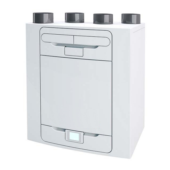
Operation and Monitoring Operation and Monitoring Product Description Mechanical Ventilation/Heat Recovery (MVHR). This heat recovery unit is designed for the energy efficient ventilation of houses and similar dwellings, conforming to the latest requirements of the Building Regulations document F 2010. The unit is designed for continuous 24 hour extract ventilation of stale moist air from bathrooms, toilets, utility rooms and kitchens. -
Page 5: Controlling The Unit
Operation and Monitoring Controlling the unit The unit can be controlled via the Touch screen display, via WiFi, switched inputs, or via a third party building control system. Touch screen display The touch screen display can be located on the front of the unit or connected to the unit via a remote docking kit. The Control Unit provides the user interface for commissioning and monitoring purposes. -
Page 6: User Controls
Operation and Monitoring User controls User Menu Home Screen The user menu home screen, consists of a User Mode (BOOST) button, a Machine status bar, and a Settings / Performance bar. The Machine status scrolls through Mode of operation, Summer bypass status and Frost protection status. -
Page 7: Settings And Performance
Operation and Monitoring Settings and Performance Settings Scroll through the settings using the & buttons and select using where applicable to access Language, Date, Time, Reset filter, Display settings, Summer Bypass, Mode Scheduling, Service phone, Commissioner Menu & Diagnostics. Days Run and Filter check are reported values and do not have editable parameters in this section. - Page 8 Operation and Monitoring Time Change the time using the buttons on the screen. Note: The clock is 24 hour Clean/Replace Filter After maintenance or replacement of the filters, the filter timer can be reset by pressing NOW. Press LATER to return to the Settings Menu. Display Settings Change the brightness of the touch screen using buttons.
- Page 9 Operation and Monitoring The outdoor temperature is the minimum air temperature that the bypass will permit. This is to prevent cold draughts. Change the outdoor temperature using the buttons on the screen. This is the mode the bypass will switch to when activated.
- Page 10 Operation and Monitoring Adjust the start and finish times for each day using buttons. Silent Hours Silent Hours mode is useful to impose a speed/flow restriction on the unit to minimise unwanted noise during the night. If Silent hours are enabled, the unit will not speed up above the set Maximum Mode.
- Page 11 Operation and Monitoring Diagnostics Scroll through the Diagnostics list using the & buttons to access the following information. Machine Status, Days Run, Filter Check, Bypass, Energy Consumption, Air flows, Option boards. Input status, Output Status, WiFi Status, WiFi signal. Note: Optional upgrades may be necessary to view all information.
-
Page 12: Control Unit Screens Summary
Operation and Monitoring Control Unit Screens Summary The following Control Unit screens are available for daily operation and monitoring of the unit. Colour and visual appearance may be different to the below depending on model version and region. MVHR Installation and User Guide 476930... -
Page 13: Control Unit Screens Summary
Operation and Monitoring Control Unit Screens Summary The following Control Unit screens are available in the Settings / Performance section. Colour, visual appearance, and some features may be different to the below depending on model version and region. MVHR Installation and User Guide 476930... -
Page 14: Maintenance
Maintenance Maintenance Filter Maintenance Heat recovery units require regular maintenance. This unit has been designed to facilitate access to enable maintenance to be carried out easily. When the unit displays “Clean or replace filters”. This is a reminder to ensure that the filters are not so dirty that they are blocking the airflow or allowing dirt to pass through. -
Page 15: Periodic Maintenance
Maintenance Periodic Maintenance WARNING THE FAN AND ANCILLARY CONTROL EQUIPMENT MUST BE ISOLATED FROM THE POWER SUPPLY DURING MAINTENANCE. Fan Filters Check fan filters as described on the previous page. Heat Exchanger Cell Step 1: Remove the outer cover by pressing the tabs either side of the control module and lifting the cover outwards from the bottom edge. -
Page 16: Spares
Maintenance Spares The following spare parts may be ordered from Vent-Axia: Part No Description 472663 Main Power Board 472665 Control Module 472667 Filters G3, 2 per pack 472669 Filters M5, 1 per pack 472671 Filters F7, 1 per pack 472673... -
Page 17: Troubleshooting
Troubleshooting Troubleshooting Diagnosing a Problem In the event of a problem, always troubleshoot the unit according to: Warning code displayed on the control unit. A warning code is advisory and will not immediately stop the function of the unit. Fault code displayed on the Control Unit. - Page 18 Troubleshooting Room Too Cold Screen The Room Too Cold screen displays the status of the fan. If the heating system in the building fails or is switched off and the internal temperature drops below 5°C, the unit will stop running so as to not bring cold air into an already cold house.
-
Page 19: Installation
Installation Installation Overview Before installation of the unit We advise installers to fix all mains and sensor wiring along with any internal accessories prior to fixing the MVHR unit in position, leaving approximately 500mm tails to allow for internal routing. Inspect the Unit When taking delivery of the unit, check the items delivered against the enclosed delivery note. -
Page 20: Wall Mounting The Unit
Installation Wall Mounting the Unit Top of unit Step 1: Mark the wall bracket position using the dimensions shown. Note the position of the top of the unit in relation to the wall bracket. Ensure the bracket position is horizontal. Step 2: Attach the wall bracket to the wall using appropriate fixings. -
Page 21: Floor Mounting The Unit
The board may then be attached to joists, flooring, or equivalent. Vent-Axia recommend that where possible, the wall bracket is used in conjunction with any floor mount solution to prevent the unit from tipping. -
Page 22: Floor Mounting The Unit (Alternate Method)
Installation Floor Mounting the Unit (Alternate Method) Step 1: The unit has 44 x 12mm deep fixing holes on the underside suitable for a No.6 screw. The holes are configured to allow fitment of most standard kitchen foot types (not supplied). -
Page 23: Vertical Discharge Condensate Installation
Installation Vertical Discharge Condensate Installation Note A trap must be fitted between the condensate drain of the unit and the rest of the waste system. A waterless trap is recommended, as they are not susceptible to drying out during warmer periods when no condensate is formed. -
Page 24: Attaching The Ducting
Installation Attach the Ducting 1. Always use a short piece of insulated flexible duct maximum 150 mm long, extended to its full length when connecting to ductwork. 2. Securely connect the ducting to the spigots using worm-drive clips or suitable plastic ties. -
Page 25: Electrical Installation
Installation Electrical Installation WARNING THE ENSURE THE ELECTRICAL SUPPLY AND CONTROLS ARE ISOLATED FROM THE POWER SUPPLY BEFORE REMOVING ACCESS COVERS Step 1: Remove the outer cover by pressing the tabs either side of the control module and lifting the cover outwards from the bottom edge. -
Page 26: Connect Switches And Sensors
Installation Connect Switches and Sensors The unit can be switched to boost by applying 240V to the LS input . Note: Alternative switches and inputs can be achieved by adding optional input accessories to the printed circuit board. See Accessories on page 42 for further details. For good EMC engineering practice, any sensor, switched live or Volt free cables should not be installed within 50mm of other cable or on the same metal cable tray as other cables. - Page 27 Installation Other means of connecting the unit may be used if they meet the local wiring regulations. SEE NOTES ON THE NEXT PAGE Terminal No. Name Description REMOTE Remote Terminals for connecting a remote external to the unit. Switch 1 Volt-free contact for sensor input between + and - terminals Red Light Emitting Diode A LED driving signal output between the + and –...
-
Page 28: Connect The Power Supply
Installation Connect the Power Supply WARNINGS 1. MAINS SUPPLY VOLTAGES (220-240 V AC) ARE PRESENT IN THIS EQUIPMENT, WHICH MAY CAUSE DEATH OR SERIOUS INJURY BY ELECTRIC SHOCK. ONLY A SUITABLY QUALIFIED PERSON SHOULD CONNECT THE POWER SUPPLY TO THIS UNIT. 2. -
Page 29: Commissioning
Commissioning Commissioning Powering up the Unit Switching On To switch the unit on: 1. Switch on the power at the mains supply isolator feeding the unit. 2. Following switch-on, the fan motors will start and the Control Unit will display a start-up screen, described on page 29. -
Page 30: Modifying Settings
Commissioning Modifying Settings If settings need to be changed after the unit has been commissioned, access to the commissioning menu can be accessed by following the steps below. Start up screen Every time the unit is powered up, the start up screen appears as the software loads showing the display version. -
Page 31: Commissioning Screens Summary
Commissioning Commissioning Screens Summary The following pages show all available settings within the commissioning menu. Please note that some settings may not be available, or may be in a different order, due to pre-configuration by your distributer. A Quick Start sequence will appear when powering up the unit for the first time. MVHR Installation and User Guide 476930... - Page 32 Commissioning MVHR Installation and User Guide 476930...
-
Page 33: Modifying Commissioning Settings
Commissioning Modifying Commissioning Settings Country Select country – This will load any pre-determined national default parameters for all subsequent screens. Language Select language – The language choice does not affect the defaults setup by the country choice. Load USB Settings Settings can be automatically loaded to the unit via the USB port. - Page 34 Commissioning Unit configuration Select the orientation of the unit depending on the configuration of the installation. Units with a preheater are preconfigured from the factory and cannot be changed. See page 18 for a description of the unit handing. Press to save and return to the commissioning menu.
- Page 35 Commissioning Mode Names The names and speed for each mode can be changed if required. Note: The user mode 1, Normal, is not editable. Scroll through the settings using the & buttons and select the mode pre-set for each User mode.
- Page 36 Commissioning Port Allocation The unit will automatically detect the following inputs: Wired to the lighting Current sensors Momentary switch Note: Number of available ports and port types may differ from image shown depending on unit specification. Select the Port to view the Go To Mode (speed setting), Delay and Over-run parameters.
- Page 37 Commissioning Summer Bypass See page 59 for a full description of the Summer Bypass modes and functions Select the required bypass mode. The indoor temperature setting is the maximum desired room temperature. This should be set to 3° above the central heating temperature. Change the indoor temperature using the buttons on the screen.
- Page 38 Commissioning Internal RH Trip The integral humidity sensor increases airflow speed in proportion to relative humidity levels. The sensor also reacts to small but rapid increases in humidity, even if the normal trigger threshold is not reached. The night time relative humidity setback feature suppresses nuisance tripping as humidity gradually increases with falling temperature.
- Page 39 Commissioning Frost Protection Frost Protection is required to prevent condensate freezing in the heat exchanger at low temperatures. The process is fully automatic. The method used for frost protection will depend on the model and building it is installed in. For buildings with a leak rate of 3m /hr or less (at 50Pa), a balanced frost protection mode must be...
- Page 40 Commissioning Mode Scheduling Use a schedule to set a Mode (Airflow setting) for a fixed, repeated period. For example, set Boost Mode every morning between 7:00am and 8:00am while cooking breakfast. Select the Schedule to view the settings Scroll through the settings using the &...
- Page 41 Commissioning Service Phone The Service Phone screen enables the installer to enter the telephone number that should be called for service in the event of a unit fault or for routine maintenance. Enter the number using the buttons on the screen, Scroll through the number using the buttons.
-
Page 42: Commissioning The Unit Via Usb
Commissioning Commissioning the Unit via USB When carrying out commissioning on multiple similar installations, commissioned settings may be downloaded and saved onto a USB at the end of the setup routine (see page 40). They can then be uploaded onto subsequent units saving time on site. -
Page 43: Accessories
Volt-Free Input Switch PCB Accessory 472697 The optional Input Switch Accessory offers four volt-free pairs of switch terminals to allow boosting from manual switches or a full range of Vent-Axia controllers e.g. humidistats, PIRs and timers. • Switched Live expansion PCB Accessory 472699 The optional Switched Live (LS) expansion accessory offers two extra switched live inputs (LS2 and LS3) for boosting via light switches (220-240V AC) or Normal/Boost switch. -
Page 44: Wifi Controller
The WiFi controller is a plug & play accessory that fits next to the control module. It allows the user instant access to commissioning, configuration, direct monitoring and control of the MVHR unit, using a smart phone or tablet with the Vent-Axia Connect app, available from the iTunes Store or on Google Play. Device Compatibility The app is compatible with the following iOS devices: •... - Page 45 Accessories Understanding the product label AP SSID The name of the wireless network hosted by the WiFi controller when it is not configured to communicate online. DEVICE ID The name the WiFi module identifies as when selecting a device to configure from the App.
- Page 46 Accessories Troubleshooting LED Status Description Actions Solid blue Initialising Slow blue flash Connecting to a wireless network None - normal operation Solid green Connected to a wireless network Fast green flash Active communication with a connected network Solid yellow WiFi controller is hosting a temporary Connect phone or tablet to the AP SSID network, without a device currently (network name) indicated on the WiFi...
-
Page 47: Input Switch Accessory
Accessories Input Switch Accessory WARNING THE FAN AND ANCILLARY CONTROL EQUIPMENT MUST BE ISOLATED FROM THE POWER SUPPLY DURING ANY MAINTENANCE AND WHEN FITTING THIS CONTROL MODULE. The volt free Input Switch accessory board has four inputs for volt free contacts, allowing up to four independent switched inputs to be used. - Page 48 Accessories 4. Connect the lead from Input Switch PCB into the socket on the left hand side of the PCB marked “I/P VentWise”. 5. For cable routing from the switches into the unit, refer to the electrical installation instruction on page 25. Connect the lead from each switch into the terminal block, one wire in the + and the other in the -.
-
Page 49: Switched Live Expansion Pcb Accessory
Accessories Switched Live Expansion PCB Accessory WARNING THE FAN AND ANCILLARY CONTROL EQUIPMENT MUST BE ISOLATED FROM THE POWER SUPPLY DURING ANY MAINTENANCE AND WHEN FITTING THIS CONTROL MODULE. The LS2/3 accessory board has two independent LS (Switched live) inputs which can be connected to switches on different circuits to the power circuit of the MVHR unit. - Page 50 Accessories 4. Connect the lead from LS2/3 PCB into the socket J21 shown below. 5. For routing the wires into the unit reference the electrical installation instruction on page 25. 6. From the required circuit, take the switched live and the neutral. Connect the switched live wire to the terminal marked LS2 and the neutral wire to the terminal marked NS2.
-
Page 51: Analogue Input Pcb Accessory
Accessories Analogue Input PCB Accessory WARNING THE FAN AND ANCILLARY CONTROL EQUIPMENT MUST BE ISOLATED FROM THE POWER SUPPLY DURING ANY MAINTENANCE AND WHEN FITTING THIS CONTROL MODULE. The analogue input (I/O) PCB accessory has two 0-10V inputs for proportional sensors, and two 0-10V outputs for proportional dampers. - Page 52 Accessories 4. Connect the lead from Analogue I/O PCB into the socket marked “Analogue I/O” shown below. 5. For routing the sensor leads into the unit, reference the electrical installation instruction on page 25. 6. For the siting of the Temperature, Humidity and CO2 proportional sensors refer to their instructions.
-
Page 53: Wired Remote Docking Kit Accessory
Accessories Wired Remote docking Kit Accessory WARNING THE FAN AND ANCILLARY CONTROL EQUIPMENT MUST BE ISOLATED FROM THE POWER SUPPLY DURING ANY MAINTENANCE AND WHEN FITTING THIS CONTROL MODULE. The Wired Controller Docking Kit is designed so that the Control Module on the MVHR unit can be mounted remotely. - Page 54 Accessories 5. For routing the cable from the Docking module into the Kinetic Advance, reference the electrical installation instruction in the “Installation & Commissioning” document supplied with your unit. The cable should be routed in on the left hand side of unit. 6.
-
Page 55: Connecting An Opto-Coupler
Accessories Opto-coupler Accessory WARNING THE FAN AND ANCILLARY CONTROL EQUIPMENT MUST BE ISOLATED FROM THE POWER SUPPLY DURING ANY MAINTENANCE AND WHEN FITTING THIS CONTROL MODULE. Connecting an Opto-coupler The LED terminals are intended to drive a remote LED to indicate that a fault has occurred. They provide a LED driving signal output between the + and –... - Page 56 Accessories Connect the other end of the lead to the LED + &- terminals on the Kinetic unit PCB. Please ensure that the + goes to + and the – goes to -. MVHR Installation and User Guide 476930...
-
Page 57: Flow Rate Settings
Technical data Flow Rate settings The Sentinel Kinetic Advance has four (4) user defined speeds in addition to the non-adjustable Maximum speed. User defined speeds can be assigned a Mode name from the list below. (some options may not be available in your region) Night time Normal (Unit default operating mode) -
Page 58: Summer Bypass Mode
Technical data Summer Bypass Mode The Sentinel Kinetic Advance includes a Summer Bypass (SBP) feature to bypass the heat exchanger to provide cooling when the desired Indoor Temperature is above the ambient temperature. Note that the volume of air provided by a ventilation system is a fraction of that required for space heating or space cooling and will not in itself be sufficient to cool a room. -
Page 59: Product Dimensions
Technical data Product Dimensions Figure 2: Dimensions Remove front cover (see page 24) to view Rating label. (Label is positioned to the right of the controller). MVHR Installation and User Guide 476930... -
Page 60: Spares
Technical data Spares The following spare parts may be ordered from Vent-Axia: Part No Description 472663 Main Power Board 472665 Control Module 472667 Filters G3, 2 per pack 472669 Filters M5, 1 per pack 472671 Filters F7, 1 per pack... -
Page 61: Default Settings
Technical data Default settings Parameters Settings Commissioning Screens Country United Kingdom Language English. Date Automatic - Factory set Time Automatic GMT/BST - Factory set Unit configuration Right Hand Filter Check 12 months Summer Bypass Normal Mode Names Normal, Boost, Low, Purge User Mode Boost Supply/Extract 50 %... - Page 62 Technical data Product fiche Name: Vent-Axia 405215 Advance S 405216 Advance SX Model ID (Stock Ref.) : 476808 Advance Sp LH 476809 Advance Sp RH SEC Class SEC Value ('Average') -43.03 SEC Value ('Warm') -17.88 SEC Value ('Cold') -87.71 Label Required? (Yes/No=Out of scope)
- Page 63 MVHR Installation and User Guide 476930...
-
Page 64: Disposal
Vent-Axia guarantees its products for two years from date of purchase against faulty material or workmanship. In the event of any part being found to be defective, the product will be repaired, or at the Company’s option replaced, without charge, provided that the product:- •...
Need help?
Do you have a question about the Advance SX and is the answer not in the manual?
Questions and answers