Table of Contents
Advertisement
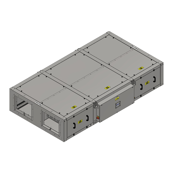
Sentinel Apex
Commercial Heat Recovery
Installation, Operation & Maintenance
Original Instructions
PLEASE READ THESE INSTRUCTIONS CAREFULLY
BEFORE COMMENCING INSTALLATION OR OPERATION.
PLEASE REFER TO ACCOMPANYING DOCUMENTATION FOR
INFORMATION SPECIFIC TO YOUR UNIT.
PLEASE RETAIN THESE INSTRUCTIONS WITH THE PRODUCT.
1
Stock Ref. N°
HR06X
HR10X
HR15X
HR21X
Copyright © 2023 Vent-Axia. All rights reserved.
HR06RX
HR10RX
HR15RX
HR21RX
Advertisement
Table of Contents
Troubleshooting


Need help?
Do you have a question about the Sentinel Apex HR06X and is the answer not in the manual?
Questions and answers