Table of Contents
Advertisement
Quick Links
Advertisement
Table of Contents

Related Manuals for Vent-Axia Sentinel Kinetic 200ZP


Summary of Contents for Vent-Axia Sentinel Kinetic 200ZP
- Page 1 Sentinel Kinetic 200ZP Kinetic 200ZPH Kinetic 200ZPM Installation & Commissioning Model Stock Ref. N° 200ZP 407161 200ZPH 407162 200ZPM 407476 PLEASE RETAIN THESE INSTRUCTIONS WITH THE PRODUCT. Copyright © 2009 Vent-Axia Limited. All rights reserved.
- Page 3 Warnings & Safety Information IMPORTANT SAFETY INFORMATION 8. Young children should be supervised to PLEASE READ THESE ensure that they do not play with the INSTRUCTIONS CAREFULLY appliance. BEFORE COMMENCING INSTALLATION. INSTALLATION GUIDANCE 1. Do not install this product in areas where 1.
-
Page 4: Table Of Contents
Contents UK Building Regulations (ADF) Product Description Declaration of Conformance Sentinel Kinetic 200ZP, 200ZPH & 200ZPM ........4 The Sentinel Kinetic conforms to the 2010 Building Technical Data Regulations (Approved Document F - Means of Ventilation) ... -
Page 5: Product Description
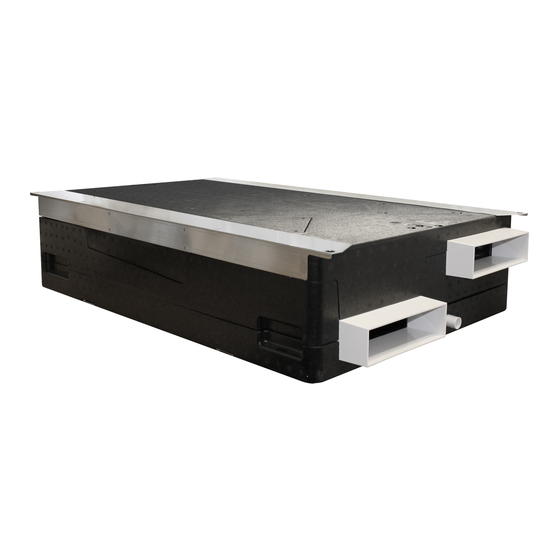
Product Description Sentinel Kinetic 200ZP, 200ZPH & 200ZPM The Vent-Axia Sentinel Kinetic Mechanical Ventilation / Heat Recovery (MVHR) heat recovery unit is designed for the energy efficient ventilation of houses and similar dwellings, conforming to the latest requirements of the Building Regulations document F 2010. -
Page 6: Technical Data
Technical Specification & Installation Technical Data Performance Sentinel Kinetic 200ZP 200ZPH & 200ZPM Airflow See Graph below Power AC Voltage Input 220-240 V AC (single phase) AC Frequency Input 50 Hz nominal Supply Fuse 3 A (located in fused spur) -
Page 7: Before Installation Of The Unit
When taking delivery of the unit, check the items delivered against the enclosed delivery note. Inspect the unit for damage in transit. If in doubt, contact Customer Services. Each box contains a Kinetic unit, anti-vibration mounts and product documentation. In addition the Sentinel Kinetic 200ZP and ZPH models include a remote control and cable. - Page 8 Technical Specification & Installation Unit Dimensions Sentinel Kinetic MVHR Installation & Commissioning...
- Page 9 Technical Specification & Installation Ceiling Mounting Step 1: Mark out and drill four fixing holes in concrete ceiling slab. Step 2: Insert four fixing studs in holes. For ceilings made of other materials use appropriate fasteners Step 3: Fit anti vibration mounts Step 4: Offer unit up to studs and tighten nuts Sentinel Kinetic MVHR Installation &...
- Page 10 Technical Specification & Installation Step 5: Duct Layout: Always use a short piece of flexible ducting 100-150mm long, extended to its full length when connecting to ductwork. Securely connect this ducting to the spigots using worm-drive clips or cable ties and duct tape. Insulate any ducting passing through an unheated space to prevent any heat losses and surface condensation.
- Page 11 Technical Specification & Installation Electrical Installation Connect the Wired remote Control 1. The Wired remote Control is supplied with a 15 metre long cable to connect to the unit; it can be permanently mounted in a living space for the end user or used for commissioning the unit. 2.
- Page 12 Technical Specification & Installation Accessing Control Terminals BEFORE COMMENCING ENSURE UNIT IS DISCONNECTED FROM THE MAINS SUPPLY Stage 1: Remove retaining screws from electrical enclosure Stage 2: Slide enclosure to its lower position Stage 3: Remove cover screws and enclosure cover Stage 4: Connect sensor and switch cables to terminals.
- Page 13 Connect any switches or sensors required to control the unit by connecting to the terminal connectors at the bottom of the control board as shown below and in Table 1. If necessary contact Vent-Axia regarding the wiring and fixing of accessories and sensors.
- Page 14 Technical Specification & Installation Table 1: Terminal Connections Name Description S/W1 Switch 1 With link fitted on J6 - activates volt-free contact for sensor input between + and - terminals S/W2 Switch 2 S/W3 Switch 3 With Vent-Wise PCB fitted to J6 - enables Vent-Wise sensor input Note do not fit standard sensors or Volt- free switch contact in this mode.
- Page 15 NOTE Power supplied to the unit via a three pole isolating switch, such as Vent-Axia Part Number 563518, must be supplied via the same circuit as the LS connection. Alternatively an isolator relay controller, part number 442030, may be used. The live supply to the unit should be fused at 3A.
-
Page 16: Powering Up The Unit
Start Up Powering Up the Unit Switching On To switch the unit on: 1. Switch on the power at the mains supply isolator feeding the unit. 2. Following switch-on, the fan motors will start and the Remote Wired Control will display a series of start-up screens, described below. -
Page 17: Start-Up Screens
Start Up Start-up Screens Sentinel Kinetic Version Screen The Sentinel Kinetic Version screen displays the firmware version number for 3 seconds. No adjustments are possible on this screen. Language Screen The Language screen displays the language used for Language the screens. It is typically displayed for 5 seconds, or English longer if changing the setting. - Page 18 Start Up An interval can be set, see page 29, at which the unit Check Filter reminds the user to check the filters. The normal 30 % screen top line will include Check Filter as a reminder to check and, if necessary, clean or replace the filters. When this has been done, press and hold the buttons for 5 seconds to reset the automatic message.
- Page 19 Start Up Purge Screen Pressing and holding the button for approximately 5 Purge 120m seconds activates purge mode when you want to purge 100 % air from the building. The unit will revert to normal flow by pressing and holding the button again for 5 seconds.
- Page 20 Start Up Indoor Temp Screen From the Normal Airflow screen, simply press the Indoor Temp button until the Indoor Temp screen is displayed. 25 C The Indoor Temp screen enables you to choose the target room temperature in degrees Centigrade – only displayed when the bypass is fitted.
-
Page 21: Commissioning
Commissioning Commissioning Overview The instructions in this section are intended to provide configuration and operation information for setting up the equipment. In the event of problems, see Troubleshooting on page 35 Follow good practice when commissioning the unit. Ensure that the system is installed according to the system designer’s intent incorporating any acoustic ducting, that all joints are airtight, ducting is well supported, bends are avoided close to vents, and that the vent valves are fully open at the start of the commissioning process. - Page 22 Commissioning Wired remote Control Screens Summary Commissioning Screens PIN number set Security PIN? Start-up Screens Proportional **** Humidity PIN number not set Sub-menus Boost Supply Proportional 50 % Language English Sub-menus Boost Extract Control Mode SW4 Momentary if fitted 50 % Sub-menus if fitted Airflow Units...
-
Page 23: Commissioning Screens
Commissioning Commissioning Screens The commissioning screens enable you to configure the operational settings of the unit. Settings are stored in a non-volatile memory and will be retained irrespective of mains supply breaks. Note: Access to the commissioning screens is prevented if the display shows Antifrost Active, Heating Failure or a Fault Code. - Page 24 Commissioning Normal Supply Screen The Normal Supply screen enables you to set the Normal Supply Normal airflow speed for the Supply fan in order to 30 % balance out any differences in ductwork or other installation features. Default Normal speed = 30% The Normal speed cannot be set below Low speed or above Boost speed setting.
- Page 25 Commissioning Boost Overrun Screen The Boost Overrun screen enables you to set a time Boost Overrun period for the fans to boost airflow (in minutes) after the 15 m light switch (LS input) is turned off. It will then return to normal airflow.
- Page 26 Commissioning Normal On/Off Screen (Day) The Normal Airflow mode can be set to run during the Normal On daytime i.e. from 6am to 11pm, the Low Airflow mode 00:00 00:00 will then run during the night from 11pm to 6pm. (Day) (On) The Normal On/Off screen enables you to set a time for...
- Page 27 Commissioning Proportional 1 Screen The Proportional 1 screen enables the conditions of the Proportional proportional sensors to be set. Humidity The unit can receive a 0-10 V proportional signal from either a humidity, CO or temperature external sensor, when connected to terminals P1. By default, the Proportion 1 input is set for a humidity sensor operation.
- Page 28 Commissioning Proportional 2 Screen By default, the Proportional 2 input is set to CO sensor Proportional operation. See Proportion 1 Screen for a description. SW4 Screen Momentary closure (1 sec) starts or stops boost for set SW4 Momentary time. Selectable range: min. = 15, max. = 30. Default = Off when no Vent-Wise card fitted.
- Page 29 Commissioning Summer Bypass Screen The Summer Bypass screen is factory set if one has Summer Bypass been fitted. It will only need resetting if a replacement Not Fitted control board has been fitted. Available options = Not fitted (default) and Fitted. Antifrost Screen The Antifrost screen is only displayed if a summer Antifrost...
- Page 30 Commissioning Filter Life Press and then use the push-buttons to Filter Service select the time between Filter Services. The options are Suburban Urban (6 months), Suburban (default: 12 months) or Rural (18 months). BMS screen On for BMS (default) or Off for Wired Remote Control, BMS Mode automatically set up by BMS signal or Wired Remote Control when either is plugged into BMS RJ11 socket.
- Page 31 Commissioning Table 3: Default Settings Parameters Settings Start-up Screens Software version Language English. Airflow Units Commissioning Screens Security PIN Not set Boost Supply/Extract 50 % Normal Supply/ Extract 30 % Low Supply/Extract Cooker Hood supply / extract 100% Cooker Hood Antifrost On but can be set Off Priority Boost Overrun...
-
Page 32: Maintenance
Maintenance Maintenance Heat recovery units, by their very nature, require regular maintenance. The Sentinel Kinetic 200ZP, 200ZPH and 200ZPM have been designed to facilitate access to enable maintenance to be carried out easily. WARNING THE FAN AND ANCILLARY CONTROL EQUIPMENT MUST BE ISOLATED FROM THE POWER SUPPLY DURING MAINTENANCE. - Page 33 Maintenance Filter Maintenance Prise Filter Covers loose using finger slots. Filter Covers Remove Filter Covers. Filters can now be pulled out using the attached Ribbons. Clean Filters gently by tapping or carefully using a vacuum cleaner if necessary. Filters can now be pushed back into their slots and the covers replaced.
- Page 34 Maintenance Heat Exchanger Maintenance Warning disconnect from mains supply before proceeding. Remove condensate drainpipe. Caution: some water may pour from the drain and pipe during this operation Remove the six case sleeve nuts and the two washers and retain for reassembly.
-
Page 35: Spares
Failure to do this will affect the unit’s performance Re attach the lower case to the unit and fasten the screws Spares The following spares can be ordered from Vent-Axia: Description Part No 200ZP, 200ZPH & 200ZPM... -
Page 36: Troubleshooting
Maintenance Troubleshooting Diagnosing a Problem In the event of a problem, always troubleshoot the unit according to: Fault code displayed on the Control Unit. Fault LED if connected. If no indications are displayed, then troubleshoot problem according to the fault symptom as described in the following tables. -
Page 37: Appendix: Options And Accessories
Appendix Appendix: Options and Accessories Sensor An optional wall-mounted CO Sensor (433257) may be used to control airflow. The CO sensor measures the level in ppm (parts per million) and the unit adjusts the fan speed accordingly. When the CO level is below the lower threshold (adjustable), the fan will run at Normal speed. - Page 38 Appendix Product Fiche Kinetic 200 ZPH ‐ Kinetic 200 ZPM ‐ Model ID (Stock Ref.) : Kinetic 200 ZP ‐ 407161 407162 407476 SEC Class A A A SEC Value ('Average') ‐38.03 ‐38.03 ‐38.03 SEC Value ('Warm') ‐13.90 ‐13.90 ‐13.90 SEC Value ('Cold') ‐80.93 ‐80.93 ‐80.93 Label Required? (Yes/No=Out of scope) Yes Yes Yes Declared as: RVU or NRVU/UVU or BVU RVU/BVU RVU/BVU RVU/BVU Speed Drive Variable Speed Variable Speed Variable Speed Type HRS (Recuperative, Regenerative, None) Recuperative Recuperative Recuperative ...
- Page 40 IF CLAIMING UNDER TERMS OF GUARANTEE Please return the complete product, carriage paid to your original supplier or nearest Vent-Axia Centre, by post or personal visit. Please ensure that it is adequately packed and accompanied by a letter clearly marked “Guarantee Claim” stating the nature of the fault and providing evidence of date and source of purchase.
Need help?
Do you have a question about the Sentinel Kinetic 200ZP and is the answer not in the manual?
Questions and answers