Advertisement
Quick Links
Download this manual
See also:
User Manual
Advertisement

Subscribe to Our Youtube Channel
Related Manuals for Vent-Axia AIR MINDER PLUS


Summary of Contents for Vent-Axia AIR MINDER PLUS
- Page 1 WHOLE HOUSE HEAT RECOVERY UNIT Installation, Connection and set up Instructions READ INSTRUCTIONS IN CONJUNCTION WITH ILLUSTRATIONS PLEASE SAVE THESE INSTRUCTIONS...
-
Page 2: Pre-Installation
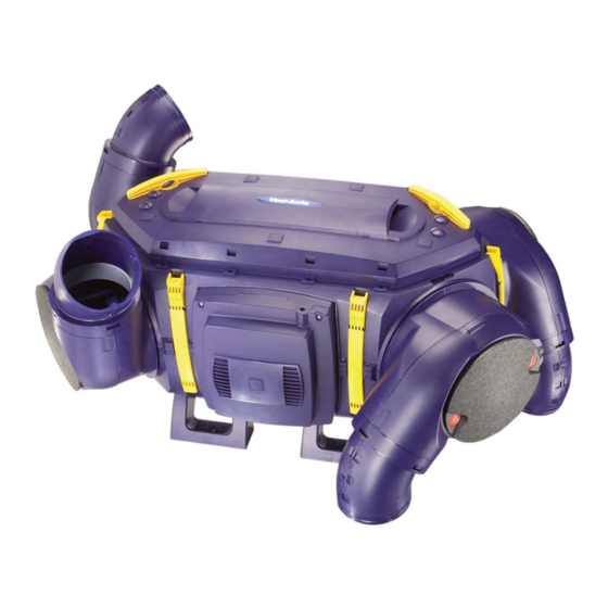
Installation and Wiring Instructions for Air Minder Plus Heat Recovery Unit (HRU). IMPORTANT: READ THESE INSTRUCTIONS BEFORE COMMENCING THE INSTALLATION DO NOT install this product in areas where the following may be present or occur: Excessive oil or a grease laden atmosphere. - Page 3 AIRMINDER PLUS has been designed and packaged to be easily installed by one person. For ease of handling and installation the Air Minder Plus HRU is delivered in two cartons: Carton 1 CARTON 1 ITEM 1 1 – MAIN BODY 2 –...
- Page 4 ASSEMBLY. 1. Fit the four feet to the Base Housing for floor fixing. 2. Insert the Heat Recovery Cube into the Base Section and secure the Cube into position. 3. Pull out the four Spigot Locking Clips. 4. Locate the Fan Blower Units (Item 8) from carton 2 either side of the Electrical Control Box, and the Inlets (Item 9) into the retaining grooves on the other side of the Base Housing.
-
Page 5: Typical Mounting
MOUNTING Note: Ensure that horizontal units are installed with a 5° fall towards the condensate drain point. TYPICAL MOUNTING 1. The HRU should be secured to the support timbers by 4 Woodscrews (25mm long x N°10 Round Head) 2. The angled brackets assembled with the Anti Vibration Mountings supplied to be attached to the feet of the HRU orientate to the diagram below for loft or ceiling mounting. - Page 6 (Colour: Orange) (Colour: Green) EXTRACT SUPPLY (Warm Stale Air) (Cold Fresh Air) from the Dwelling Intake from Outside (Colour: Yellow) (Colour: Red) DISCHARGE SUPPLY (Cold Stale Air) (Warm Fresh Air) Electrcal to the to Outside Control Box Dwelling CONDENSATE DRAIN. Installation.
-
Page 7: Installing The Controller
INSTALLING THE CONTROLLER Insert a small flat bladed screwdriver into the small slot at the base of the controller, push the release catch in and gently lever upwards to remove the front cover of the controller by pulling the cover away from the back box. -
Page 8: Mains Connection
Connections. External Sensor Connector (Where appropriate) Internal Summer Bypass Temperature Pre-Connected Sensors (If Fitted) 1 Phase Supply (Pre-Connected) (220-240V 50Hz). Dip Switches 3A FUSE Controller Connector A B C D CON 7 BOOST JP 200 (Colour: Yellow) (Colour: Red) HRU Control Panel Motor Connections FANS. - Page 9 INSTALLER SET UP INSTRUCTIONS FOR THE CONTROLLER Switch on the power at the Switch Spur Box to provide the power to the Heat Recovery Unit. On start up the screen will display: S e t C l o c k S e t o c k S u n...
- Page 10 The medium and boost inlet and extract flows can be adjusted independently via the controller as described in the Fitting and Wiring information. House size 1 Air Minder Plus 290 rate numbers and corresponding Medium 80 4...
- Page 11 E x h a u s t Press `SET’ to adjust intake rate, `SET’ again for Exhaust rate and SET again to store the new values. Air Minder Plus 290 rate numbers and corresponding House size 1 Airflow rates, Nominal setting shown bold...
- Page 12 EXTERNAL SENSOR CONNECTIONS Select the required External Sensors. Ambient Response Humidity Sensor (56 35 50) Ecotronic 1 Phase Supply (220-240V 50Hz). Humidity Sensor (56 35 32) 3A FUSE L.C.D Controller Visionex PIR (45 07 26) A B C D CON 7 BOOST JP 200 A B C D...
- Page 13 ‘Guarantee Claim’ stating the nature of the fault and providing proof of the date and source of purchase. As part of the policy of continuous product improvement Vent-Axia reserve the right to alter specifications without notice Head Office: Fleming Way, Crawley, West Sussex RH10 9YX...
Need help?
Do you have a question about the AIR MINDER PLUS and is the answer not in the manual?
Questions and answers