Table of Contents
Advertisement
Quick Links
Advertisement
Table of Contents

Subscribe to Our Youtube Channel
Related Manuals for HME Clear-Com ProGrid PG8-INTERCOM-FX


Summary of Contents for HME Clear-Com ProGrid PG8-INTERCOM-FX
- Page 1 PG8-INTERCOM-FX and PG4-INTERCOM-FX User Guide PN: 399G093 Rev B 10/22/14...
-
Page 2: Document Reference
The product described in this document is distributed under licenses restricting its use, copying, distribution, and decompilation/reverse engineering. No part of this document may be reproduced in any form by any means without prior written authorization of Clear-Com, an HME Company. -
Page 3: Table Of Contents
Contents Document Reference......................2 Important Safety Instructions ............... 5 Operating and Storage Temperature ............... 5 Eye Safety ....................... 5 Safety symbols ....................6 Device Description ..................7 Front Panel ....................9 PG8-INTERCOM-(CC/485/444)-FX ..............9 PG4-INTERCOM-(CC/485/444)-FX ..............9 Rear Panel ....................11 PG8-INTERCOM-(CC/485)-FX .............. - Page 4 Auxiliary Ports – R485/GPIO ................. 18 RS232 Connection ..................18 RS485 Connection ..................18 Connector Hood Specification ............... 18 USB Connection .................... 18 LAN Connection .................... 19 9.10 Word Clock Connection ................. 19 9.11 Power Connection ..................19 9.12 Hardware Connection Example 1 – Remote intercom key-panels, interfaces and wireless base stations ............
-
Page 5: Important Safety Instructions
Important Safety Instructions Read these instructions. Keep these instructions. Heed all warnings. Follow all instructions. Do not use this apparatus near water. Clean only with dry cloth. Do not block any ventilation openings. Install in accordance with the manufacturer’s instructions. Do not install near any heat sources such as radiators, heat registers, stoves, or other apparatus (including amplifiers) that produce heat. -
Page 6: Safety Symbols
Safety symbols Familiarize yourself with the safety symbols in Figure 1: Safety symbols. These symbols are displayed on the apparatus and warn you of the potential danger of electric shock if the system is used improperly. Figure 1-1: Safety symbols PG8-INTERCOM-FX and PG4-INTERCOM-FX User Guide... -
Page 7: Device Description
Device Description The PG8/PG4-INTERCOM-FX series was developed in cooperation with some of the world’s leading manufacturers of intercom systems and are fully compatible with Clear-Com or RTS intercom matrixes, user key-panels and interfaces. The PG8/PG4-INTERCOM-FX can be ordered with different quantity and types of inputs and outputs. For Clear-Com intercom systems: PG8-INTERCOM-CC-FX with... - Page 8 The low latency, synchronous, ProGrid network provides the capacity to transport and route up to 1024 audio inputs into thousands of outputs over a redundant network. Redundant fibre connections are established using the two LC multimode, or single mode, 1Gbit or 2 GBit optical transceivers. The dual redundant ring topology uses the advantages of fibre optical transmission in temporary and permanent applications, especially where long distance transport and high-quality audio are required.
-
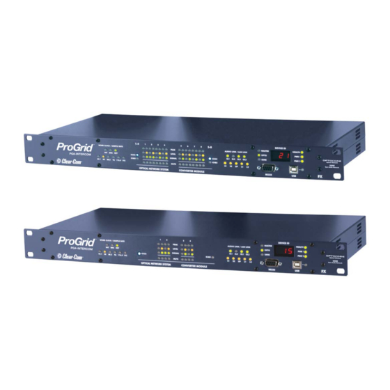
Page 9: Front Panel
Front Panel PG8-INTERCOM-(CC/485/444)-FX PG4-INTERCOM-(CC/485/444)-FX Word Clock LED: Indicates the selected word clock source: INT: Internal word clock – The device is a system master BNC: External word clock via the BNC WC input NET: Word clock received from the network Intercom and Signal Monitor for the 8 Duplex Channels (4 Duplex Channels for V3R): IC422: Four-wire intercom ports with bi-directional RS422 (for Clear-Com) - Page 10 Device ID Display: The identification number (ID) of the device HEALTH LED: Green: Power supply to the device works, temperature is within limits PWR 1 LED: Green: Power supply 1 is operational and receiving power PWR 2 LED: Green: Power supply 2 is operational and receiving power USB connector: USB connection for remote control from a computer USB LED:...
-
Page 11: Rear Panel
Rear Panel PG8-INTERCOM-(CC/485)-FX PG4-INTERCOM-(CC/485)-FX RS485/GPIO: 4 x RS485/GPIO (D-Sub-9) auxiliary port for data transmission Word Clock IN: BNC Word clock input allowing synchronization of ProGrid devices/network from an external word clock source Word Clock OUT: BNC Word clock output for synchronization of external devices POWER 2: Mains input for power supply 2 (100 …... -
Page 12: Intercom-444-Fx
PG8-INTERCOM-444-FX PG4-INTERCOM-444-FX RS485/GPIO: 4 x RS485/GPIO (D-Sub-9) auxiliary port for data transmission Word Clock IN: BNC Word clock input allowing synchronization of ProGrid devices/network from an external word clock source Word Clock OUT: BNC Word clock output for synchronization of external devices POWER 2: Mains input for power supply 2 (100 …... -
Page 13: Device Details
Device Details IC422 and IC485 - Intercom Ports Each four-wire intercom port is complete with a line level input, line level output and a bi-directional RS422 or RS485 (device specific) serial communication link, allowing seamless integration with Clear-Com or RTS intercom systems. The intercom ports are duplicated with a reversed pinout (TO MATRIX and TO PANEL) to allow connections to intercom matrix frames, user key-panels and interfaces using straight Cat5 cables. -
Page 14: Transmission Delay
Transmission Delay The ProGrid system delay, including the matrix, is a fixed 41.6 µs @ 48 kHz for all channels. The additional transport delay per ProGrid unit on the network (<200 ns) is insignificant in comparison. Overall system delay is dependent on the converters used and the length of network cables in the system. -
Page 15: Control
Control All system and device parameters are configured using the Optocore Control software. The system can be configured and controlled centrally, over the ProGrid network, with the exception of the initial configuration of the unique identifier (ID) of the device. The Optocore Control software is capable of running multiple instances on the same PC or by using the Optocore Control software’s Client/Server mode. -
Page 16: Channel Allocation
Channel Allocation The standard bandwidth allocation of an ProGrid network is as follows: 256 Channels @ 48 kHz – 1 Gbit network Audio 768 Channels @ 48 kHz – 2 Gbit network RS485 Data 32 Channels Video 3 CVBS Video Channels * Ethernet 100 MBit Fast Ethernet * * If the network is used for Ethernet transport the system is reduced to 1 CVBS video channel. -
Page 17: Sane Bandwidth Allocation
SANE bandwidth allocation The standard bandwidth allocation of a SANE link is as follows: Audio 64 Channels @ 48 KHz Ethernet 100 MBit Fast Ethernet PG8-INTERCOM-FX and PG4-INTERCOM-FX User Guide... -
Page 18: Connectors And Cables
Connectors and Cables Intercom Ports – CC/485 Use shielded twisted pair cable (Cat-5, Cat-5e, Cat-6) terminated with RJ-45 connectors. Connect intercom matrix to ports labelled TO MATRIX and intercom user key-panels and interfaces to ports labelled TO PANEL. Optical Connections Multimode transceivers connected using a 50 µm OM3 fibre cable can be used for applications requiring cable lengths of up to 700 m (worst case). -
Page 19: Lan Connection
LAN Connection Use a shielded twisted pair cable (Cat-5, Cat-5e, Cat-6) with RJ-45 connectors. 9.10 Word Clock Connection Use 75 Ω coaxial cable with BNC connectors. 9.11 Power Connection Use power cords with IEC C13 connectors. 9.12 Hardware Connection Example 1 – Remote intercom key- panels, interfaces and wireless base stations The following example demonstrates the use of PG8/PG4-INTERCOM-FX devices with intercom matrix systems. -
Page 20: Hardware Connection Example 2 - Remote Line Level Audio And Gpio
9.13 Hardware Connection Example 2 – Remote line level audio and GPIO The following example demonstrates the use of PG8/PG4-INTERCOM-FX devices with intercom matrix systems. A PG8-INTERCOM-FX is connected to eight four-wire ports of a central intercom matrix. The four-wire ports, along with GPIO control signals (device dependent), are distributed over the fully routable ProGrid redundant ring topology network to remote locations. -
Page 21: Hardware Connection Example 3 - Trunking Between Intercom Matrixes
9.14 Hardware Connection Example 3 – Trunking between Intercom Matrixes The following example demonstrates the use of PG8/PG4-INTERCOM-FX devices to link intercom matrixes. A pair of PG8-INTERCOM-FX devices is used to establish an eight channel trunk between two intercom matrixes. The four-wire ports are transported over a fully routable ProGrid redundant ring topology network. -
Page 22: Hardware Connection Example 4 - Two-Wire Partyline Intercom Over Progrid
9.15 Hardware Connection Example 4 – Two-wire PartyLine intercom over ProGrid The following example demonstrates the use of PG8/PG4-INTERCOM-FX devices to distribute two-wire PartyLine intercom over ProGrid using four-wire to two-wire PartyLine intercom interfaces. This example shows a ProGrid redundant ring topology network consisting of four PG4-INTERCOM-FX devices connected to third party four-wire to two-wire interfaces. - Page 23 Please note: Systems from these examples may be seamlessly integrated with all BroaMan DiViNe, ProGrid and SANE interfaces, such as the PG32-AES-FX, PG2-MADI-C-FX and PG2- MADI-F-FX devices, PG16-FX/TP and PG8-FX/TP networkable converters. Please note: Audio can be routed to and from any ProGrid device on the on the network. Audio can be routed from an intercom device to any MADI, AES/EBU or analog output on the network.
-
Page 24: Starting Up
Starting Up 10.1 Software Installation Installation requirement for the software is a functioning computer system with Microsoft Windows 2k (Requires installation of GDIplus.dll), XP 32&64Bit, Vista 32&64Bit, Server2003&2008, Windows7 32&64Bit or Mac: Intel based Macs with above OS using Bootcamp/Parallels/VMWare. The computer should be equipped with an USB interface for configuration and remote controlling, and a RS232 interface (or an appropriate USB / RS232 converter) for firmware upgrade. - Page 25 lowest ID and word clock input acts as word clock master of the network, when present. • Clock Setup: All devices in the network must work with the same sample rate. CLOCK SOURCE allows the selection of Auto (BNC priority), INT (internal) or BNC (external) word clock signal. •...
-
Page 26: Connection Tables
Connection Tables Pin-out Four-Wire Intercom port - TO PANEL – Clear-Com (IC422) Channel Audio In Audio Out RS422 In RS422 Out Use this pin-out only for devices loaded with Clear-Com modules (IC422) RJ-45 Pin-out Four-Wire Intercom port - TO MATRIX – Clear-Com (IC422) Channel Audio In Audio Out... - Page 27 Pin-out Four-Wire Intercom port - TO MATRIX - RTS / Telex (IC485) Use this pin-out only for devices loaded with Channel Audio In Audio Out RS485 RTS / Telex modules (INTERCOM-485) * Shows the standard pinout for RS485 on the 485 module.
- Page 28 Pin-out Auxiliary Port - 4 x RS485 Please verify the correct polarity of adaptors. RS485 Channel Software configurable for duplex (RS485) or simplex (RS422) operation. An adaptor must be constructed for connectivity to MIDI, GPIO and CAN interfaces. D-Sub-9- female Locking system acc.
- Page 29 Pin-out Optical Fibre-Port Optocore MADI SDI* * Assumes standard Input / Output transceiver. Non-standard Input / Input and Output / Output transceivers for SDI video I/O are available LC and SC connectors Pin-out RS232 - Port RS232 Power Internally Channel Use standard RS232 cable, bridged +5VS...
-
Page 30: Technical Specifications
Technical Specifications Hardware standard: CC/485: FCC-RJ45 Intercom 444: D-SUB 37 Female, D-Sub 37 Male 10kΩ Analog Line Input Impedance IC422/IC485/IC444 Maximum input level +18 dBu 115 dB (A-weighted) ≥ 100dB THD+N @ -1dBFS 45kΩ Analog Line Output Impedance IC422/IC485/IC444 Maximum output level +18 dBu 115 dB (A-weighted) ≥... - Page 31 Power supply Type Switch-mode, universal input Mains voltage 100 … 240 V Frequency 50 … 60 Hz Power consumption Depending on the configuration of the device, 32VA - Max Security classification Class 1: basic insulation, connected to the protective grounding conductor Security regulations Harmonised European standard EN60065 Mains connector...
-
Page 32: Dimensions And Weight
Dimensions and Weight Front panel: width 483 mm / 19 inch height 44 mm / 1.73 inch depth 200 mm / 7.87 inch Rear panel: width 438 mm / 17.25 inch Weight 2.7 kg ≡ 4.41 lbs Modifications that serve the purpose of technical improvement of the device may be carried out without prior notification. -
Page 33: Compliance
Compliance FCC notice This device complies with Part 15 of the FCC rules. Operation is subject to the following two conditions: (1) This device may not cause harmful interference, and (2) This device must accept any interference received, including interference that may cause undesired operation. NOTE: This equipment has been tested and found to comply with the limits for a Class A digital device, pursuant to Part 15 of the FCC rules. - Page 34 August 13, 2005. Manufacturers, distributors and retailers are obliged to finance the costs of recovery from municipal collection points, reuse, and recycling of specified percentages per the WEEE requirements. Instructions for Disposal of WEEE by Users in the European Union The symbol shown below is on the product or on its packaging which indicates that this product was put on the market after August 13, 2005 and must not be disposed of with other waste.
-
Page 35: Warranty And Liability
Warranty and Liability The Clear-Com product that you have purchased is covered by the Clear-Com Standard Limited Warranty, the terms and conditions of which can be found at www.clearcom.com/support/warranty-support-policies. We encourage you to review the Standard Limited Warranty to determine its coverage, exclusions from coverage and duration.
Need help?
Do you have a question about the Clear-Com ProGrid PG8-INTERCOM-FX and is the answer not in the manual?
Questions and answers