
Related Manuals for HME PRO850


Summary of Contents for HME PRO850
-
Page 1: Wireless Intercom
HME# 400G568 Rev B 9/30/05 PRO850 Wireless Intercom Operating Instructions Base Station Version A.3.1x... -
Page 2: Table Of Contents
PDA850 Installation ............................41 PDA850 Operation ............................41 END-USER LICENSE AGREEMENT FOR HME PRO850 SYSTEM SOFTWARE ........42 LIMITED WARRANTY ............................46 © 2005 HM Electronics, Inc. The HME logo and product names are registered trademarks of HM Electronics, Inc. All rights reserved. - Page 3 Exposure Environment, for work-related use. Transmit only when person(s) are at least the minimum distance from the properly installed, externally mounted antenna. Hereby, HM Electronics, Inc. declares that the PRO850 is in compliance with the essential requirements and other relevant provisions of EMC Directive 89/336/EEC.
-
Page 4: Section 1. Introduction
SECTION 1. INTRODUCTION PRO850 equipment operates in the UHF band from 470 MHz to 740 MHz in 18 MHz subsets. Transmitters and receivers operate in different, non-adjacent 18 MHz bands. Synthesized frequencies can be selected in 25 kHz increments over each 18 MHz band, for 720 transmit and 720 different receive frequencies. -
Page 5: Equipment Features
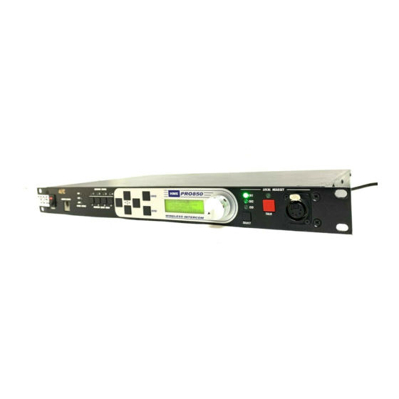
EQUIPMENT FEATURES Base Station Front Panel Features 3 4 5 11 12 13 14 POWER switch CANCEL button (backs out of menus or cancels operation) BELTPAC CONFIGuration connector (RJ10 telephone handset cable connector) Display screen WIRED STATUS lights 10. Multi-function knob (headset volume control; CH1 = Channel 1 intercom status adjustment for specific menu selections) CH2 = Channel 2 intercom status... -
Page 6: Beltpac Top Panel Features
Beltpac Top Panel Features 2 3 4 5 8 9 10 11 12 Master power/volume control “D” function light “A” button “B” light – indicates Channel 2 active Power and battery condition indicator “D” button “C” button 10. Transmit light – indicates transmitter on “A”... -
Page 7: Block Diagrams
BLOCK DIAGRAMS Base Station Beltpac... -
Page 8: Equipment Specifications
EQUIPMENT SPECIFICATIONS Base Station GENERAL ⎯ Frequency Range: 470-608 MHz, 614-740 MHz in 18 MHz Tx and Rx bands Frequency Response: 50 Hz to 10 kHz Power Requirements: 100-240VAC, 50-60Hz or 12-14VDC Temperature Range: 32-122°F (0-50°C) Size: 19” x 1.72” x 11.5” (1-RU) (48.26 x 4.37 x 29.21 cm) Weight: <11 lbs. -
Page 9: Beltpac
RECEIVER ⎯ Type: 720 synthesized, 25 kHz channel steps RF Sensitivity: <1µV for 20dB SINAD Squelch: Adjustable Image Rejection: 60dB Squelch: Data channel coded plus carrier signal level Squelch Quieting: 90dB Frequency Stability: 10 ppm Distortion: <1% at maximum deviation Antenna Type: ¼-wave whip (supplied) or external (BNC connector) Beltpac... -
Page 10: Factory Defined Frequencies
Factory Defined Frequencies Band 9 Band 1 Band A Band 2 Band C Band 4 Beltpac Tx Base Tx Beltpac Tx Base Tx Beltpac Tx Base Tx Base Rx Beltpac Rx Base Rx Beltpac Rx Base Rx Beltpac Rx Group/ Freq. -
Page 11: Frequency Plan
Frequency Plan PRO850 frequency bands (MHz) along with US TV channel assignments. Base and Beltpac use corresponding band pairs: 0 & 8, 1 & 9, 2 & A, 3 & B, 4 & C, 5 & D, 6 & E Antenna marking colors are shown in parenthesis. -
Page 12: Section 2. Equipment Setup
(if present) around the antenna should match the color dot (if present) near the connector on the base. USB Interface Connector — To interface the PRO850 with a PC using a computer interconnect cable with a USB 1.1 compliant type-B connector, connect the cable from this connector to the PC. This is a pre-planned product improvement, and not currently available. - Page 13 This control is active even if the 4-wire only mode is selected. 10. Channel 1 RJ45 4-wire Intercom Interface Connector — Use this RJ45 connector for 600Ω balanced interface of PRO850 Channel 1 with other cabled intercoms. Pin designations are as follows.
-
Page 14: Section 3. Pro850 Operation
NOTE: Be sure the base station is not on the air when you turn the power on. To do this, press and hold the CANCEL button while you press the power switch. Hold the CANCEL button until HME flashes on and off the display screen. -
Page 15: Display Screen Navigation
Display Screen Navigation , ENTER and CANCEL buttons and the control To navigate through PRO850 screen displays, use the knob adjacent to the screen as follows. Use the arrow buttons to move through horizontal selections on the bar at the top of the main menu, and to move to the left and right on advanced screens. -
Page 16: Display Screen Functions And System Settings
Display Screen Functions and System Settings Base Configuration Settings Configuration displays provide customized configuration settings for the base station and Beltpacs. They also allow you to save your settings to a file for future access. Advanced settings are provided for output mixing, alert signals and paging capabilities. - Page 17 Base Station Receiver Frequency: Frequencies P1 – P4, S1 – S4 and T1 – T4 are preset in the system and cannot be changed. Frequencies U1 – U16 can be set by the user. Select receiver RX1 – RX4, then select a frequency for that receiver.
- Page 18 Base Station Transmitter Frequency: Frequencies P1 – P4, S1 – S4 and T1 – T4 are preset in the system and cannot be changed. Frequencies U1 – U16 can be set by the user. Select transmitter TX1 or TX2, then select a frequency for that transmitter.
- Page 19 Base Station Intercom Configuration: Select intercom Ch1 or Ch2, then use the up and down buttons to select what Mode the intercom is in; “OFF,” “4-Wire Only” or “2-Wire/4-Wire.” Select the Ch Lvl box, and use the control knob to adjust the input gain level.
- Page 20 Frequency Scan: Connect a Beltpac to the BELTPAC CONFIG connector on the front panel of the base station to enable scanning of base transmit frequencies. In this operation, the Beltpac and base station receivers are scanned to find the cleanest group of frequencies for the base station to transmit on, and they are assigned to Tx1 and Tx2 in the base station.
-
Page 21: Beltpac Configuration Settings
Base Station Dial Adjustment Setting: Select Fine or Coarse for the control knob, for mix level dial adjustments. In the Fine mode, mix level adjustments made by the control knob occur in 0.25dB increments. In the Coarse mode, they occur in 2.25dB increments. Beltpac Configuration Settings Beltpac configuration settings are stored in the base station, but do not become effective until they are uploaded into individual Beltpacs. - Page 22 Beltpac Receiver Frequency: Select the desired Beltpac and the receiver frequency for that Beltpac’s operation (P1-4, S1-4, T1-4 or U1-16. If U1-16 is selected, use the control knob and the up and down arrow buttons to select the desired frequency, in 25kHz increments. NOTE: When only one receiver is present, it will switch between the two frequencies as needed.
- Page 23 Beltpac Buttons C and D Setup: Select the Beltpac and the Mode (Off or Momentary) for Buttons C and D on each Beltpac. ISO1 = * Talk, to Beltpacs receiving only Tx1 ISO2 = * Talk, to Beltpacs receiving only Tx2 = Talk, to Beltpacs receiving both Tx1 and Tx2 Page = Talk, Page (stage announce) Aux = Talk, Auxiliary Out...
- Page 24 Copy Beltpac Settings: To copy settings from one Beltpac to all others for all settings except ID numbers, names and transmit frequencies, select Copy and press the ENTER button. Upload Beltpac Settings: To upload all Beltpac settings from the base station to a Beltpac, select a Beltpac then select the upload box and press the ENTER button.
-
Page 25: Saving And Loading Configurations
Saving and Loading Configurations Save Configuration Settings to File: To save your configuration settings to a file, select the File number and press the ENTER button. Select Save and press the ENTER button again. NOTE: File number 1 is reserved for frequency scans. -
Page 26: Advanced Configuration Settings
Advanced Configuration Settings Auxiliary Output Mixing: Select the box next to Ch1, Ch2, Aux and/or Mic to enable input, then use the control knob to adjust output level in 0.25dB or 2.25dB increments for the desired mix. Place the cursor to the left of the bar below Aux:dB and use the control knob to adjust the overall Aux audio output level in 1.5dB increments. - Page 27 Page Output Mixing (continued): Select the box(es) next to Rx1-Rx4, then use the control knob to adjust output level in 0.25dB or 2.25dB increments for the desired mix. Check these boxes only if you want receiver audio continuously fed to the Page Output. Leave them unchecked for normal operation.
- Page 28 Headset Output Mixing (continued): Select HSL (headset left) or HSR (headset right), then select the box(es) next to Rx1-Rx4 to enable input. Use the control knob to adjust output level in 0.25dB or 2.25dB increments for the desired mix. Check these boxes only if you want receiver audio continuously fed to the Headset Output.
-
Page 29: Status Displays
Status Displays Status displays provide information indicating the status of the system, or of parts or functions of the system. Transmitter Status: Select transmitter 1 or 2, then press the ENTER button to obtain the status of the selected transmitter. Receiver Status: Select receiver 1 through 4, then press the ENTER button to observe signal and tuning... -
Page 30: Monitor Displays
Monitor Displays Monitor displays provide input/output levels and input level adjustments for all devices connected to the base station. Monitors Audio Levels at Base Station Inputs: Select the desired input source, then move the curser to the bar at the top of the screen. Use the control knob to adjust the audio input level from the selected source in 1.5dB increments. -
Page 31: Diagnostic Tests
Diagnostic Tests To perform a Subcarrier Transmitter Test, with the cursor at the BP box, enter a Beltpac ID number then select Start. Let the test run for a few seconds then press the ENTER button to stop it. The results will be shown at the right side of the display. -
Page 32: Advanced Configuration
ADVANCED CONFIGURATION Because of its advanced digital signal processing, the PRO850 is very flexible and can be configured to fit the needs of any installation. This section covers some of the available configurations. Auxiliary Input and Output Functions: The base station auxiliary input and output are used for different purposes depending on the system configuration. -
Page 33: Cascading Multiple Base Stations
Master and Slaves allows audio routing requests and status to be communicated. The PRO850 supports two methods of distributing audio from the Slaves to the Master. These are called “Aux Distributed” and “2-Wire Distributed”. Each approach has its own advantages and disadvantages. For a quick temporary setup where not all features are required, “Aux Distributed”... -
Page 34: 2-Wire Distributed Set Up
2-Wire Distributed Set Up When a system is configured for 2-Wire Distributed operation, it has most of the features of a stand-alone base. However, the wiring is somewhat more complex and there are still some feature limitations. In this mode, receiver audio from the Slave bases is distributed by way of the auxiliary inputs and outputs as well as the 2-wire intercom lines. -
Page 35: Beltpac Operation
BELTPAC OPERATION Controls and Buttons Master On/Off Volume Control Turns Beltpac on and off. Controls volume levels and beep intensity. Press and hold control button in to mute primary receiver input. A and B Buttons Perform functions set up in Beltpac programming. If set up for Lock function, press and release button in less than one second to lock on. -
Page 36: Indicator Lights
Indicator Lights Power/Battery Light Remains lit when power is on. Green = good batteries Amber = low batteries Red = nearly dead batteries C and D Lights On while any functions programmed into C and D buttons are activated. Transmit Light On steady red while Beltpac is transmitting. -
Page 37: Connectors And Adjustment
Connectors and Adjustment Headset Connector XLR type connector. Antenna Connectors Transmitter antenna connector has color dot (or none), matching color band (or none) on transmitter antenna. Receiver antenna connector has color dot (or none), matching color band (or none) on receiver antenna. Screw antennas securely into connectors. -
Page 38: Batteries
To change batteries: Infrared Window The infrared window provides capability for interfacing with a PDA for easy PRO850 configuration setups. Optional HME PDA850 software is required. Dual-Receiver Operation A Beltpac equipped with the optional second receiver operates a little differently from a single-receiver Beltpac. -
Page 39: Troubleshooting
Troubleshooting If a Beltpac fails to communicate with the base, check the following items • Be certain it has fresh batteries, is on, and is within range of the base station. • Verify that the Beltpac receiver frequencies, Rx1 and Rx2 are set to the corresponding base transmit frequencies. -
Page 40: Section 4. Pro850 System Software
® Beltpac configuration settings on a PC and save the settings to files. An RS-232 interface cable must be used to connect the PRO850 base station to the PC in which PC850 software is installed. PDA850 is a Palm OS application for remote configuration of individual Beltpacs. -
Page 41: Pc850 Operation
PC850 can be operated in either of two modes: Offline or Online. Offline means that the program is operated without any connection to a PRO850 base station. In this mode, the only screens that can be accessed are under the Configuration tab. This allows a user to set up configurations and save them to disk so that they can be loaded into the base station later. - Page 42 two types of connections are shown: Manual connections and dynamic connections. Manual connections result from configuration settings or functions. Dynamic connections result from Beltpac operations or the front panel Talk button. Checking a box in the window always results in a manual connection. Manual connections are not overridden by dynamic operations.
-
Page 43: Pc850 Wizard
PC850 Wizard The PC850 provides a wizard to simplify configuring your PRO850 system. This wizard is integrated with the PC850 to take you through a series of steps to set up both your base station and Beltpacs. The wizard helps... -
Page 44: Pda850 Installation
SECTION 5. PDA850 INSTALLATION Minimum Requirements for Use of PDA850 Software • • Palm compatible PDA with IrDA port Minimum of 1 megabyte of available RAM • • Palm OS 3.5 or later A PC with the ability to Hot Sync to the PDA ®... -
Page 45: End-User License Agreement For Hme Pro850 System Software
IMPORTANT — READ CAREFULLY: This HME End-User License Agreement ("AGREEMENT") is a legal agreement between you (either an individual or a single entity) and HM Electronics, Inc. (“HME”) for the HME software product PRO850 System Software, which includes computer software and may include associated registration files, media, printed materials, sample documents, and "online"... - Page 46 3) UPGRADES. If the SOFTWARE PRODUCT is labeled as an upgrade, you must be properly licensed to use a product identified by HME as being eligible for the upgrade in order to use the SOFTWARE PRODUCT. A SOFTWARE PRODUCT labeled as an upgrade replaces and/or supplements (and may disable) the product that formed the basis for your eligibility for the upgrade.
- Page 47 CUSTOMER REMEDIES. HME’s and its suppliers’ entire liability and your exclusive remedy shall be, at HME’s option, either (a) return of the price paid, if any, or (b) repair or replacement of the SOFTWARE PRODUCT that does not meet HME’s Limited Warranty and which is returned to HME with a copy of your receipt.
- Page 48 RESELLER OR DEALER TO YOU WHETHER EXPRESS OR IMPLIED. Should you have any questions concerning this AGREEMENT, or if you desire to contact HME for any reason, please contact us: HM Electronics, Inc., 14110 Stowe Drive, Poway, California, 92064, U.S.A.
-
Page 49: Limited Warranty
LIMITED WARRANTY HM Electronics, Inc. (“HME”) warrants the PRO850 for a period of three (3) years* from the date of purchase against defects in materials or workmanship provided it was purchased from an authorized dealer. During the warranty period, defective HME Products will be repaired without charge for parts and labor. Simply return the defective HME Product with your sales slip as proof of the date of purchase. - Page 50 The WEEE Directive covers most HME products being sold into the EU as of August 13, 2005. Manufacturers, distributors and retailers are obliged to finance the costs of recovery from municipal collection points, reuse, and recycling of specified percentages per the WEEE requirements.
Need help?
Do you have a question about the PRO850 and is the answer not in the manual?
Questions and answers