
Related Manuals for HME Clear-Com EQUIP G30238-3A1


Summary of Contents for HME Clear-Com EQUIP G30238-3A1
- Page 1 Installation Guide EQUIP ™ Wireless Intercom PUB-00178 Rev B 7/18/22 © 2022 HME Clear-Com Ltd. All rights reserved.
-
Page 3: Table Of Contents
Additional Information � � � � � � � � � � � � � � � � � � � � � � � � � � � � � � � � � � � � � � � � � � � � � � � �14 © 2022 HME Clear-Com Ltd. All rights reserved. -
Page 5: Introduction And System Overview
When you tap on a sidebar menu option you are prompted to enter a PIN or you can use the LOG IN menu option to enter the PIN� This PIN is provided by Clear-Com� Record this PIN here: © 2022 HME Clear-Com Ltd. All rights reserved. -
Page 6: Headset Overview
Push-to-Talk mode: Press and hold any audio button (1, 2 or Group Chat) to use in this mode (there is an audible single-tone confirmation). Release to cease communication and exit this mode (there is an audible two-tone confirmation). Table 2 © 2022 HME Clear-Com Ltd. All rights reserved. -
Page 7: Installing The System
"Advanced" J3800 J805 XCVR 1 button and "proceed to��" to continue� J800 J801 J802 © 2022 HME Clear-Com Ltd. All rights reserved. DC - 48 V DC +... -
Page 8: Ip Address
Also see "Network Connection" on page 3� Fig. 7 DHCP ON is the default� To manually set an IP address, toggle DHCP OFF to change network set- tings and populate the necessary fields. See Fig. 8. Fig. 8 © 2022 HME Clear-Com Ltd. All rights reserved. -
Page 9: Transceivers And Connecting A Transceiver To The Base Station
(1 in this example)� The green center LED indi- cates the transceiver is powered on and functional� J800 J801 J802 DC - 48 V To WALL DC + OUTLET Fig. 10 BASE STATION Base Station POWER SUPPLY opened © 2022 HME Clear-Com Ltd. All rights reserved. -
Page 10: Transceiver Placement
To put the EQUIP base station in site survey mode, go to SYSTEM>SETTINGS and select Remote Transceiver from the drop-down list (see Fig� 11)� Fig. 11 Tap the Site Survey button (see Fig� 12) and follow the onscreen prompts (Fig� 12 and 13)� Fig. 12 © 2022 HME Clear-Com Ltd. All rights reserved. -
Page 11: Overlapping Transceivers
RF space� It is important to assure that a beltpack sees no more than one transceiver with the same pair of channels in any coverage area location� Fig. 14 © 2022 HME Clear-Com Ltd. All rights reserved. - Page 12 Fig. 15 Fig. 16 Note: When setting up overlapping Roaming Zones the RF channels on each overlapping transceiv- er must be unique� Transceivers that see each other cannot use the same RF Channels� © 2022 HME Clear-Com Ltd. All rights reserved.
-
Page 13: Transceiver 5 Ghz Radio Channels
The outer port LED on the transceiver front will initially flash a different color as the EQP-TCVR scans for available channels before turning solid green once a channel is found (on the base station HOME screen, the “Transceivers” indicator is yellow while scanning before turning green)� © 2022 HME Clear-Com Ltd. All rights reserved. -
Page 14: Manually Setting 5 Ghz Channels
From the pop-up list, choose a DFS or Non-DFS channel� Fig. 22 Click the Save button to apply, this will take a few minutes to reset the transceiver and apply/dis- play changes� Fig. 23 © 2022 HME Clear-Com Ltd. All rights reserved. -
Page 15: Channel Setup - Intercom Channels
For Single Channel operation, go to SYSTEM>SETTINGS, and from the drop-down list select Chan- nel Setup, tap on the Single Channel button under Channel Setup (the selected button is blue, see Fig� 27)� Tap the "Save" button to update setting� © 2022 HME Clear-Com Ltd. All rights reserved. -
Page 16: Channel Settings
Fig. 29 Note: For additional recommendations on how to connect the EQUIP unbalanced inputs and out- puts to another 4-wire or 2-wire device, please visit www.clearcom.com/solutionfinder and look for the EQUIP FAQ's� © 2022 HME Clear-Com Ltd. All rights reserved. -
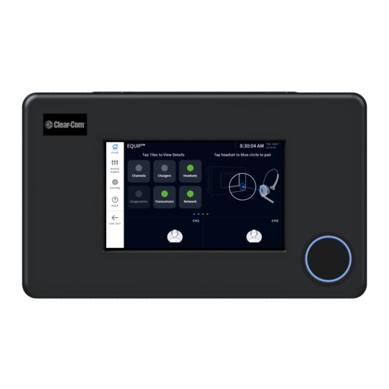
Page 17: Wireless Headsets
Note: If pairing fails (indicated by a red swirling ring), try again� Hold the headset steadily cen- tered and flush against the headset pairing ring (movement and distance from the pairing ring can cause pairing errors)� © 2022 HME Clear-Com Ltd. All rights reserved. -
Page 18: Additional Information
ADDITIONAL INFORMATION Use the contact information listed on the HELP screen or scan the QR code for additional EQUIP help and resources� Fig. 31 © 2022 HME Clear-Com Ltd. All rights reserved.
Need help?
Do you have a question about the Clear-Com EQUIP G30238-3A1 and is the answer not in the manual?
Questions and answers