Table of Contents
Advertisement
Quick Links
Advertisement
Table of Contents

Related Manuals for HME PRO850


Summary of Contents for HME PRO850
-
Page 1: Wireless Intercom
HME# 400545 Rev — 4/26/04 PRO850 Wireless Intercom Quick Start Guide... -
Page 2: Table Of Contents
HM Electronics, Inc. is not responsible for equipment malfunctions due to erroneous translation of its publications from their original English version. © 2004 HM Electronics, Inc. The HME logo and product names are registered trademarks of HM Electronics, Inc. All rights reserved. -
Page 3: Section 1. Introduction
SECTION 1. INTRODUCTION PRO850 equipment operates in the UHF band from 470 MHz to 740 Hz in 18 MHz subsets. Transmitters and receivers operate in different, non-adjacent 18 MHz bands. Synthesized frequencies can be selected in 25 kHz increments over each 18 MHz band, for 720 transmit and 720 different receive frequencies. -
Page 4: Equipment Controls And Connectors
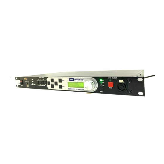
EQUIPMENT CONTROLS AND CONNECTORS Refer to the figures below and on the next page for the locations of controls and connectors. Base Station Front Panel 3 4 5 11 12 13 14 POWER switch (with LED power indicator) CANCEL button (backs out of menus or cancels operation) BELTPAC CONFIGuration connector (RJ10 telephone handset cable connector) -
Page 5: Beltpac Top Panel
Beltpac Top Panel 2 3 4 5 8 9 10 11 12 Master power/volume control “D” function indicator “A” button “B” function indicator Power and battery condition indicator “D” button “C” button 10. Transmit indicator “A” function indicator 11. “B” button “C”... -
Page 6: Equipment Setup
(#1 on front panel). The red light in the power switch and the display screen should light. After about 5 seconds, the HME logo should appear on the display screen. After another second or two, the logo will fade away and a menu will appear. -
Page 7: Section 3. Pro850 Configuration
SECTION 3. PRO850 CONFIGURATION Now that everything is connected and ready, you can begin the configuration process. Most factory default settings will not be changed. However, a few settings must be changed to make the system operational. This is because the base is shipped with the receivers disabled and all transmitters turned off. -
Page 8: Base Station Configuration
BASE STATION CONFIGURATION The following steps will guide you through a frequency scan and configuration of the base transmitters and receivers. The frequency scan will identify the best of the pre-programmed frequencies available at your location. If none of these frequencies work for your application, you will need to refer to the Operating Instructions for setting user frequencies. - Page 9 Press the right arrow button to move the cursor to the power select list. Use the up and down arrow buttons to select the desired transmit power for TX1. Choose the lowest power level that gives sufficient range. If you are unsure, choose 100 mW to start.
-
Page 10: Beltpac Configuration
11. Repeat steps 5, 6, and 7 for this Beltpac. 12. Repeat steps 10 and 11 for the remaining Beltpacs. 13. Press CANCEL twice to return to the Config menu. Congratulations! Your PRO850 system is now configured and ready to go. -
Page 11: Pro850 Operation
This section describes how to operate your newly configured PRO850 system, assuming the factory default settings. If you used other existing settings rather than factory defaults, you will need to refer to the PRO850 Operating Instructions for information regarding those settings. -
Page 12: Beltpac Audio Connectors And Mic Gain Adjustment
B Channel Indicator (Channel 2) Green while listening to channel 2 and red when talking on channel 2. C Button (Talk ISO) Press and hold to talk to all Beltpac users independent of their channel selection. C Indicator (ISO) Lights red while talking on ISO. 10. -
Page 13: Base Station Operation
BASE STATION OPERATION Refer to the figure below for the functions of the various controls in the default configuration. There may be differences if you are not using the factory default settings. Front Panel Controls, Indicators and Connectors 1. Receiver Quick Menu Buttons Press any of these buttons to access the settings for that receiver.
Need help?
Do you have a question about the PRO850 and is the answer not in the manual?
Questions and answers