Table of Contents
Advertisement
Quick Links
Advertisement
Table of Contents

Related Manuals for HME Clear-Com Encore MS-702


Summary of Contents for HME Clear-Com Encore MS-702
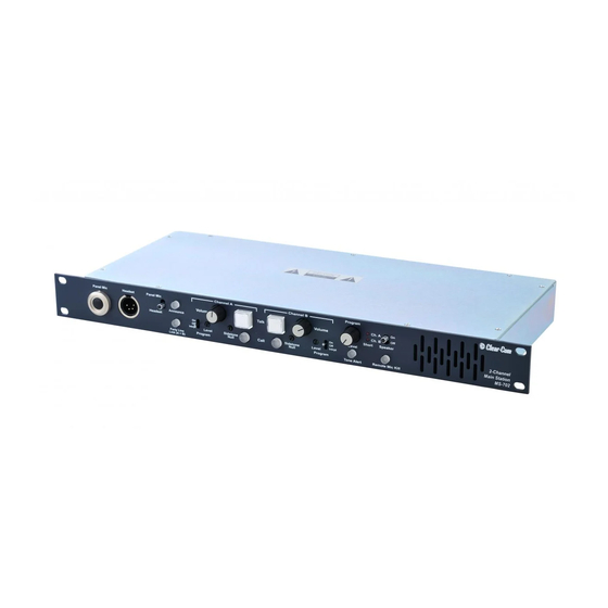
- Page 1 Encore MS-702 ™ Two-Channel Main Station Instruction Manual...
- Page 2 No part of this document may be reproduced in any form by any means without prior written authorization of Clear-Com, an HME Company. Clear-Com Offices are located in California, USA; Cambridge, UK; Montreal, Canada; and Beijing, China. Specific addresses and contact information can be found on Clear-Com’s corporate website:...
-
Page 3: Table Of Contents
CONTENTS IMPORTANT SAFETY INSTRUCTIONS OPERATION ........1-1 Introduction . - Page 4 T w o - C h a n n e l M a i n S t a t i o n...
- Page 5 IMPORTANT SAFETY INSTRUCTIONS 1. Read these instructions. 2. Keep these instructions. 3. Heed all warnings. 4. Follow all instructions. 5. Do not use this apparatus near water. Please read and follow 6. Clean only with dry cloth. 7. Do not block any ventilation openings. Install in accordance with the these instructions before manufacturer’s instructions.
- Page 6 CAUTION RISK OF ELECTRIC SHOCK DO NOT OPEN This symbol alerts you to the presence of uninsulated dangerous voltage within the product's enclosure that might be of sufficient magnitude to constitute a risk of electric shock. Do not open the product's case. This symbol informs you that important operating and main- tenance instructions are included in the literature accompanying this product.
-
Page 7: Operation
OPERATION INTRODUCTION Congratulations on choosing this Clear-Com product. Clear-Com was established in 1968 and remains the market leader in providing intercoms for entertainment, broadcast and industrial applications. The ruggedness and high build-quality of Clear-Com products defines the industry standard. In fact, The MS-702 two-channel many of our original beltpacks and main stations are still in daily use around main station is a powerful,... -
Page 8: Operation
speaker when the announce button, talk buttons or program interrupt are activated. This feature helps minimize feedback. The MS-702 also incorporates a dual-channel program interrupt system (IFB). When activated, one or more stations can interrupt the program audio to either another intercom station or a talent wearing Clear-Com’s wired or wireless talent receivers. - Page 9 Figure 1: Front Panel 1. Talk Buttons: Each channel has an illuminated talk button for activating the microphone feed to that channel. Each talk button has a dual action (momentary or latching feature) depending on how the button is pressed. If desired, the latching function for each channel can be defeated using the option switches on the rear panel.
- Page 10 button will flash while the call button is pressed, indicating the presence of a call signal on the line. 3. Tone Alert: An audible tone alert can be enabled to sound when a call signal is received on either channel. This can be useful when the operator's attention has been drawn away from the MS-702 indicator panel.
- Page 11 7. Program ON-OFF-INTRPT Switches: The program on-off-intrpt switches are used to manually or automatically control program audio feed into the intercom lines. The settings are as follows: • ON: The channel will receive program audio when the switch is set to on.
- Page 12 pressed to quiet the line in this situation. Those needing to communicate can then set their talk functions to on as needed. Note: The RMK switch can only function if the MS-702 main station is powering all of the stations in the system. The switch momentarily interrupts power to the other beltpacks and stations in the system.
-
Page 13: Rear Panel
1. Check and unscrew the set screw in the mic mounting flange to make sure it is clear of the threads in the bushing. 2. Screw the microphone into the bushing hand tight. 3. Turn the set screw on top of the mic mounting flange clockwise to lock the microphone in place. - Page 14 in normal operation. The default position of the switches is in the off (up) position. The function of each switch is as follows: 1. MOM TALK A: Setting the momentary talk A switch to the on position will disable the latching function of the channel A talk button.
- Page 15 17. Power Switch: The power switch can be used to turn AC power to the MS-702 on and off. When in the on position, the front-panel talk buttons illuminate blue. 20. AC Power Connection: An IEC type 320 connector is provided to interface to the appropriate AC power cord to be used.
- Page 16 Pin 1 --- Ground (shield) Pin 2 --- - Signal Pin 3 --- + Signal The audio output is balanced and transformer isolated. It has a 600 ohm impedance and a nominal output level of 0 dBV. A shielded twisted pair cable should be used in the cable wired to this connector.
-
Page 17: Re-Setting Program Interrupt Options
8. Connect the unit to AC mains electricity. RE-SETTING PROGRAM INTERRUPT OPTIONS When you set one of the front-panel Program ON-OFF-INTRPT switches to the INTRPT position, any talk signal activated on that channel interrupts the program audio during the talk signal. You can change this option so that activating a call signal, rather than a talk signal, interrupts the program audio for the duration of the signal. - Page 18 In the default position, the jumper plug covers pins 1 and 2, which causes talk signal activation, rather than call signal activation, to interrupt the program audio. JP5, for channel A Talk signals interrupt program audio JP6, for channel B Call signals interrupt program audio...
-
Page 19: Installation
INSTALLATION 1. Unpack the unit and inspect for any damage that may have occurred in shipping. 2. Connect the proper AC mains cable. 3. Install the MS-702. Note: For additional information, refer to the Clear-Com System Installation Manual. 4. Connect the AC to the mains circuit. Note: Information on the mains power requirement is given on the underside of the unit. - Page 20 2 - 2 C l e a r - C o m ® M S - 7 0 2 T w o - C h a n n e l M a i n S t a t i o n I n s t r u c t i o n M a n u a l...
-
Page 21: Maintenance
MAINTENANCE INTRODUCTION This chapter provides maintenance information, including a block diagram and troubleshooting tips. Caution:These servicing instructions are for use by qualified personnel only. To reduce the risk of electrical shock, do not perform any servicing other than that contained in the operating instructions unless you are qualified to do so. -
Page 22: Troubleshooting Tips
TROUBLESHOOTING TIPS SYMPTOM CAUSE SOLUTION System does not operate. Blue No AC power to the MS-702. Make sure the power switch on the talk buttons do not illuminate rear panel is turned on. Check the and short lights do not AC connection and cable. - Page 23 SYMPTOM CAUSE SOLUTION 10 Ohm chassis ground resistor is Check the DC resistance for open. 10 Ohms between the chassis and pin #1 of any intercom connector. If this condition occurs, it is because the system ground came into contact with something that was “HOT”...
- Page 24 SYMPTOM CAUSE SOLUTION Far too many terminations on the Check all main stations and power intercom line. supplies to make sure each intercom channel is terminated at only one point. Table 3-1: Troubleshooting Tips 3 - 4 C l e a r - C o m ® M S - 7 0 2 T w o - C h a n n e l M a i n S t a t i o n I n s t r u c t i o n M a n u a l...
-
Page 25: Specifications
SPECIFICATIONS dBv is an absolute measurement. 0 dBv is referenced to 0.775 V RMS. Headset Microphone Pre-Amp Input Type: Dynamic Impedance: 1KΩ Input Level: -55 dBV nominal; -10 dBV max. Frequency Response 200 Hz to 15 kHz Gain from headset mic to intercom line: +41 dB Panel Microphone Pre-Amp Input Type: Electret... -
Page 26: Rear Panel Connectors
Short Circuit Reset Time: < 15 s Hum and Noise: < -80 dBv Station Capacity Capacity: Maximum of 60 headset stations or 20 speaker stations, distributed over both channels Rear Panel Connectors Intercom: (6) XLR-3M (3 per channel) Announce Out: (1) XLR-3M (audio) Announce Relay: (1) 1/4 in. - Page 27 Weight 5.0 lbs. (2.75 kg) Notice About Specifications While Clear-Com makes every attempt to maintain the accuracy of the information contained in its product manuals, that information is subject to change without notice. Performance specifications included in this manual are design-center specifications and are included for customer guidance and to facilitate system installation.
- Page 28 4 - 4 C l e a r - C o m ® M S - 7 0 2 T w o - C h a n n e l M a i n S t a t i o n I n s t r u c t i o n M a n u a l...
-
Page 29: Limited Warranty
LIMITED WARRANTY This document details the Clear-Com Standard Limited Warranty for all new products for sale within all regions with the exception of Military, Aerospace, and Government (MAG). EXCEPT AS SET FORTH HEREIN ("LIMITED WARRANTY"), CLEAR-COM MAKES NO OTHER WARRANTIES, EXPRESS, IMPLIED OR STATUTORY, INCLUDING WITHOUT LIMITATION ANY WARRANTIES OF MERCHANTABILITY, NONINFRINGEMENT OF THIRD PARTY RIGHTS, OR FITNESS FOR A PARTICULAR PURPOSE, ALL OF WHICH ARE EXPRESSLY DISCLAIMED. -
Page 30: Warranty Period
(5) All software products, including Concert (Client and Server), ECS, Production Maestro and Logic Maestro are warranted for one year and shall substantially conform to published specifications. The media on which the Software is furnished is warranted to be free of defects in material and workmanship (under normal use) for a period of one year. -
Page 31: Liability
h) Software Upgrades Software Upgrades include new Features and/or Functional Enhancements and are not included as part of the Standard Warranty but may be purchased at the published rates. ii) Note: In the absence of a Software Update containing a program correction and no available workaround to mitigate the problem, at the discretion of Service, Sales, Engineering, or Product Management, the Customer may be provided a Software Upgrade under warranty. - Page 32 Clear-Com® Standard Limited Warranty...
Need help?
Do you have a question about the Clear-Com Encore MS-702 and is the answer not in the manual?
Questions and answers