
Related Manuals for HME Clear-ComMS-704


Summary of Contents for HME Clear-ComMS-704
- Page 1 CLEAR-COM ENCORE MS-704 FOUR-CHANNEL MAIN STATION RM-704 FOUR-CHANNEL REMOTE STATION I N S T R U C T I O N M A N U A L...
- Page 2 Legal Disclaimers All Rights Reserved Copyright © 2013 HME Clear-Com Ltd. Clear-Com, the Clear-Com logo, and Clear-Com Concert are trademarks or registered trademarks of HM Electronics, Inc. The software described in this document is furnished under a license agreement and may be used only in accordance with the terms of the agreement.
-
Page 3: Table Of Contents
CONTENTS OPERATION ........1-1 Introduction ..........1-1 The Clear-Com Concept. - Page 4 Internal Option Jumpers ........2-12 IFB Mode .
- Page 5 IMPORTANT SAFETY INSTRUCTIONS 1. Read these instructions. 2. Keep these instructions. 3. Heed all warnings. 4. Follow all instructions. 5. Do not use this apparatus near water. 6. Clean only with dry cloth. Please read and follow 7. Do not block any ventilation openings. Install in accordance with the these instructions before manufacturer’s instructions.
- Page 6 CAUTION RISK OF ELECTRIC SHOCK DO NOT OPEN This symbol alerts you to the presence of uninsulated dangerous voltage within the product's enclosure that might be of sufficient magnitude to constitute a risk of electric shock. Do not open the product's case. This symbol informs you that important operating and main- tenance instructions are included in the literature accompanying this product.
-
Page 7: Operation
OPERATION INTRODUCTION Congratulations on choosing this Clear-Com product. Clear-Com was established in 1968 and remains the market leader in providing intercoms for entertainment, educational, broadcast and industrial applications. The ruggedness and high build-quality of Clear-Com products defines the industry standard. In fact, many of our original beltpacks and main stations are still in Clear-Com manufactures daily use around the world. -
Page 8: Understanding The Ms-704/Rm-704 Main And Remote Stations
Clear-Com main stations, power supplies and certain remote stations each have an auxiliary program input with its own volume control, which allows an external audio source to be fed to the intercom system. Visual signal circuitry (call lights), a standard feature on all main and remote stations, allows the user to attract the attention of operators who have removed their headsets. - Page 9 The MS-704 is a four-channel main station that contains a no-fail system power supply. The RM-704 is a four-channel remote station intended to be powered from the intercom line. The following is a list of features found in the MS-704 and RM-704 intercom stations: •...
-
Page 10: Operation
• EXTERNAL IFB and HOT MIC OUTPUT: A rear panel jack provides direct connection to Clear-Com’s external IFB system such that the station’s microphone can be used in the external IFB system. A buffered unswitched output of the selected microphone is also available. •... -
Page 11: Intercom Power Status Lights (Ms-704)
• Listening to intercom channels • Monitoring main program • Talking on intercom channels • The all-talk function • Sending and receiving call signals • Linking intercom channels together (MS-704) • The announce function Intercom Power Status Lights (MS-704) The four red short lights are failure indicators for each of the four intercom lines. -
Page 12: Talking On Intercom Channels
If several channels are being listened to at the same time, it might be desirable to adjust the individual listen levels of each channel for the desired mix. Talking on Intercom Channels To talk on an intercom channel, press the desired talk button. Pressing and holding the button will cause the function to be active only while the button is held (momentary). -
Page 13: Remote Mic Kill Function (Ms-704)
listen latches are not reset, but the microphone’s audio does not go to the intercom line while the announce function is active. A set of relay contacts are activated to control some external device. There is an option which allows program audio to be fed to the announce output. -
Page 14: Hidden Adjustment Controls
• AUTO-TALK/LISTEN: Four DIP switches (one for each channel) enable automatically setting the listen function whenever a talk is active on the enabled channel. • TALK LATCH DISABLE: Four DIP switches (one for each channel) disable the latching action of the selected channel. •... -
Page 15: Rear Panel Options
3. Repeat the adjustment for all four channels on the station. 4. Adjust the sidetone adjust control for the desired amount of sidetone in the headset. • CHANNEL PROGRAM FEED LEVEL: Beside the null control for each channel there is a control marked PGM, which adjusts the amount of program being sent to that channel. -
Page 16: Summary Of Front-Panel Lights
unplug the intercom line connected to the affected channel and its red “short” light should go out. This indicates that there is a short in that line. Follow that intercom line and break it apart in several places while it is plugged into the station to isolate the section of line that is shorted. - Page 17 a button the feature switches on, and when you release the button the feature switches off. This is called “momentary” use. 1 - 1 1 M S - 7 0 4 / R M - 7 0 4 F O U R - C H A N N E L M A I N / R E M O T E S T A T I O N S...
- Page 18 1 - 1 2 M S - 7 0 4 / R M - 7 0 4 F O U R - C H A N N E L M A I N / R E M O T E S T A T I O N S...
-
Page 19: Installation
INSTALLATION This chapter discusses how to install the MS-704 and RM-704 intercom stations in an intercom system. INSTALLATION OVERVIEW This section describes the Clear-Com concept of intercom line interconnection. The following subjects are discussed: • Intercom line connection • Line termination •... -
Page 20: Fail-Safe Power
FAIL-SAFE POWER An intercom power supply has special needs that are not met by traditionally designed power supplies. An intercom power supply must work in adverse conditions such as low AC line voltage, momentary shorts on the DC power lines to the stations, and excessive peak loads during “power-on”conditions. The following features are incorporated into the MS-704’s power supply: •... - Page 21 limited to 2 amperes. A short on any one intercom line will not bring the whole system down. Note: Power supply lines connected together at remote stations will dis- able the individual channel short circuit protection feature. • FRONT PANEL “SHORT” LIGHTS: There are four short lights on the front panel (one for each channel).
-
Page 22: Connecting Intercom Channels On Rm-704
FAIL SAFE POWER DISTRIBUTION SCHEME WITH SINGLE-CHANNEL REMOTE STATIONS BELT BELT PACK PACK MS-704 Main Station BELT BELT PACK PACK BELT BELT PACK PACK BELT BELT PACK PACK 2 Amp Power Ch A Supply Ch B Ch C Ch D THE 4 POWER LINES ARE NOT CONNECTED Wall Station... -
Page 23: Power Distribution And Short Circuit Protection
Placing jumper plug over pins 1 and 2 connects channels A and B Placing jumper plug over pins 3 and 4 connects channels B and C Placing jumper plug over pins 5 and 6 connects channels C and D Figure 2-6: J16 Six-Pin Jumper 5. -
Page 24: Intercom Cable Considerations
is affected by blinking the red short light(s) corresponding to these channel(s). This light will assist in locating the shorted or overloaded channel. Shorts are generally caused by miswiring or damaged cables. Overloads are generally caused by connecting too many beltpacks and stations to a channel. The current requirements of Clear-Com remote stations and beltpacks vary with model and use. -
Page 25: Ground Isolation
GROUND ISOLATION The pin #1 ground connection of each XLR connector must also be isolated from the chassis. Pin #1 should not be connected to the shell of the XLR connector. Figure 2-8: Interconnect Cable Detail Note: The remote stations connected to each channel are powered from the intercom cable for that channel. -
Page 26: Physical Installation
PROGRAM IN CHANNEL A CHANNEL B HOT MIC/IFB RM-704 CHANNEL C CHANNEL D ANNOUNCE OUT Class 2 Wiring RM-704 CHANNEL B PROGRAM IN CHANNEL A Term WARNING: FIRE OR SHOCK HAZARD DO NOT HOT MIC/IFB EXPOSE THIS EQUIPMENT TO RAIN MS-704 OR MOISTURE. -
Page 27: Intercom Line Connectors (Rear Panel)
long. The microphone is of the electret type. The microphone has a built-in ¼ in. (0.64 cm) phone jack for a connector. A proprietary mating receptacle is mounted on the station. To install a GM-9 or GM-18 panel mount microphone, use the following steps: 1. -
Page 28: Announce Output (Rear Panel)
ANNOUNCE OUTPUT (REAR PANEL) An XLR-3M connector provides the announce output from the station. Whenever the announce button on the front panel is pressed, the selected microphone is sent to the announce output and the announce relay is activated. Simultaneously, if the program audio feed to the announce output is enabled, it is interrupted by the announcement. - Page 29 Figure 2-10: Accessory Connector • AUXILIARY PROGRAM INPUTS: Four different program inputs, one for each channel, are provided. These auxiliary program inputs can only be fed directly to their associated intercom line. The only controls that affect these inputs are the PGM-level controls associated with each channel and the internal program interrupt switch that is active if the function has been activated with an option DIP switch and a talk is active on that channel.
-
Page 30: Internal Option Jumpers
INTERNAL OPTION JUMPERS There are several jumper options inside the chassis of the MS-704 and RM-704. CAUTION:Remove AC power from the unit before removing the top cover. The following options are available: • IFB operation mode select • Run/test mode jumper •... - Page 31 2 - 1 3 M S - 7 0 4 / R M - 7 0 4 F O U R - C H A N N E L M A I N / R E M O T E...
- Page 32 2 - 1 4 M S - 7 0 4 / R M - 7 0 4 F O U R - C H A N N E L M A I N / R E M O T E...
-
Page 33: Maintenance
MAINTENANCE INTRODUCTION This chapter provides maintenance information, including a block diagram and troubleshooting tips. Caution: These servicing instructions are for use by qualified personnel only. To reduce the risk of electrical shock, do not perform any servicing other than that contained in the operating instructions unless you are qualified to do so. -
Page 34: Rm-704 Block Diagram
Figure 3-11: MS-704 Block Diagram RM-704 BLOCK DIAGRAM 3 - 2 M S - 7 0 4 / R M - 7 0 4 F O U R - C H A N N E L M A I N / R E M O T E S T A T I O N S... - Page 35 Figure 3-12: RM-704 Block Diagram 3 - 3 M S - 7 0 4 / R M - 7 0 4 F O U R - C H A N N E L M A I N / R E M O T E S T A T I O N S...
- Page 36 3 - 4 M S - 7 0 4 / R M - 7 0 4 F O U R - C H A N N E L M A I N / R E M O T E S T A T I O N S...
-
Page 37: Technical Specifications
TECHNICAL SPECIFICATIONS MS-704/RM-704 FOUR-CHANNEL STATIONS dBu is an absolute measurement. 0 dBu is referenced to 0.775 volts RMS Panel Microphone Input Input Type Electret Input Impedance >=2KΩ Mic Limiter Threshold 0dBu ±3dB Mic Limiter Range >= 20dB Headset Microphone Input Input Type Dynamic Input Impedance... - Page 38 Output Impedance >= 200Ω Load Impedance >= 600Ω IFB/Hot Mic Type Unbalanced Output Impedance 150Ω Load Impedance >= 600Ω Frequency Response Panel Mic - Party Line 600 - 10KHz ± 3dB Headset Mic - Party Line 200 - 12KHz ± 3dB Headset Mic - Line Out 200 - 12KHz ±...
- Page 39 Min Gain Panel Mic - Party Line <= 25dB Mains Power (MS-704) Input Voltage Range 100 - 240 VAC Input Frequency Range 50 - 60 Hz Input Power <= 60 VAC Output Voltage 30 VDC ± 0.5V Output Current per Channel (Continuous) 1.2 A Output Current per Channel (Peak) 2 A (Do not exceed the 1.2A rating...
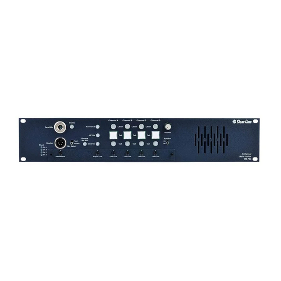
- Page 40 Front Panel Controls & Indicators (MS-704) (1) Panel / headset mic switch (1) Mic on button (1) All talk button (1) Announce button (1) Party line link button (4) Program ON-OFF-INTERRUPT DIP switches (1) Program level control (4) Listen adjust controls (4) Channel null adjust controls (4) Channel program feed adjust controls...
- Page 41 (1) Sidetone adjust control (1) Headset audio limiter DIP switch (3) Interrupt enable DIP switches (4) Auto-call DIP switches (4) Auto-talk/listen DIP switches (4) Talk latch disable DIP switches (4) Line length DIP switches Environmental 32 - 122 F (0 - 50 Dimensions (MS-704/RM-704) 19 in.
- Page 42 4 - 6 M S - 7 0 4 / R M - 7 0 4 F O U R - C H A N N E L M A I N / R E -...
-
Page 43: Limited Warranty
LIMITED WARRANTY Clear-Com warrants that at the time of purchase, the equipment supplied complies with any specification in the order confirmation when used under normal conditions, and is free from defects in workmanship and materials during the warranty period. Clear-Com offers 24 x 7 During the warranty period Clear-Com, or any service company authorized by customer support if you Clear-Com, will in a commercially reasonable time remedy defects in... -
Page 44: Warranty Repairs And Returns
period will be offered at no charge between 09:00 and 17:00 according to the customer’s local time zone. In addition, for customers who purchase an Extended Warranty or Service Contract, 24-hour customer support is offered immediately upon purchase of such agreement. For more information, contact your authorized dealer, distributor, or sales representative. -
Page 45: Non-Warranty Repairs And Returns
China Office Beijing Representative Office Beijing, P.R.China Tel: +8610 65811360 / 65815577 Clear-Com has the right to inspect the equipment and/or installation or relevant packaging. NON-WARRANTY REPAIRS AND RETURNS For items not under warranty, you must obtain an RMA by contacting the User Support Center. - Page 46 OTHERWISE, WITH RESPECT TO THE PRODUCTS OR ANY PART THEREOF DELIVERED HEREUNDER, OR FOR ANY DAMAGES AND/OR LOSSES (INCLUDING LOSS OF USE, REVENUE, AND/OR PROFITS). SOME STATES DO NOT ALLOW THE EXCLUSION OR LIMITATION OF INCIDENTAL OR CONSEQUENTIAL DAMAGES OR THE LIMITATION ON HOW LONG AN IMPLIED WARRANTY LASTS, SO THE ABOVE LIMITATIONS MAY NOT APPLY TO YOU.
Need help?
Do you have a question about the Clear-ComMS-704 and is the answer not in the manual?
Questions and answers