Table of Contents
Advertisement
Quick Links
Advertisement
Table of Contents

Related Manuals for Xterra TL200


Summary of Contents for Xterra TL200
- Page 1 TREADMILL TL200 OWNER’S MANUAL...
-
Page 2: Table Of Contents
Content Overview Drawing....................... 2 SAFETY INSTRUCTION .................... 3 2.1. Power Requirement ..................6 2.2. Level Adjustment....................7 2.3. Power Switch ....................7 2.4. Running Belt Adjustment.................. 8 2.5. Machine movement..................9 Assembly Instructions ....................10 3.1. Pre-Assembly Check List ................10 3.2. -
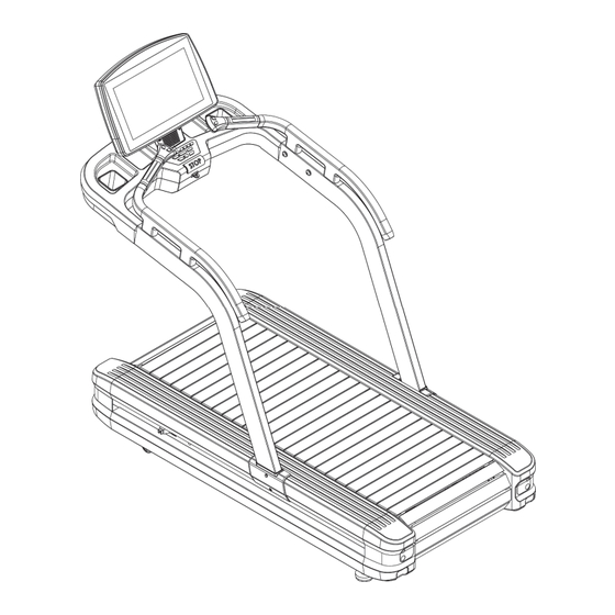
Page 3: Overview Drawing
1. Overview Drawing 2018/5/4V1.0+V1.0... -
Page 4: Safety Instruction
2. SAFETY INSTRUCTION When using this product, basic precautions should always be followed, including the following: Please read the instruction carefully before starting to use this product. DANGER – To reduce the risk of electric shock: Always unplug this product from the electrical outlet immediately after using and before cleaning. - Page 5 thin. 11 Before turning the product power off, turn all controls to the off position then remove the plug from the outlet. 12 Connect the product to a properly grounded outlet only. 13 If the power cord is damaged, be sure to ask the manufacturer for replacement to avoid accidents.
- Page 6 23 Before using this product, you should step on the it then turn on the product. Do not turn on the treadmill before step on it. 24 Running surface Width dimensions 560*1475mm 25 Customer Address 2018/5/4V1.0+V1.0...
-
Page 7: Power Requirement
2.1. Power Requirement This treadmill needs special power supply: Power Voltage(V) Frequency(HZ) Rated Current(A) 50/60 50/60 50/60 50/60 50/60 240+ 50/60 Wirings should be transported according to the electric law of the local country. High pressure wires, low pressure wires and underground wires should be transported separately and can’t connect with or twist other wires. -
Page 8: Level Adjustment
2.2. Level Adjustment The treadmill will wobble during workout and the incline angles will be affected if it is placed on uneven ground. The level adjustment method is as follows: Turn A counter-clockwise to loosen it Adjust B to the proper height Turn A clockwise to tighten it. -
Page 9: Running Belt Adjustment
2.4. Running Belt Adjustment If you need to adjust the running belt tightness, please follow these steps: After assembling and stabilizing the treadmill, check whether the running belt is running properly. First, determine that the power supply meets the requirements. After the power is plugged in, start the treadmill, press the QUICK START button, and then press the up-speed key to increase the speed to 4.0 miles per hour (MPH), or 6.4 k km/h (KPH). -
Page 10: Machine Movement
2.5. Machine movement When the machine is moving, you can put the handling tube (K) into the back of the box to move the machine. 2018/5/4V1.0+V1.0... -
Page 11: Assembly Instructions
3. Assembly Instructions Ready the operation instructions carefully before use, then choose a flat position to assemble. This treadmill also can use other way to account the HRC. When in fitness,user can wear the chest pulse belt and the HRC will show in Pulse windows. -
Page 12: Hardware Pack
3.2. Hardware Pack ITEM Description Qty ITEM Description Inner hexagon steel screw M10x25 of Umbrella head crossed screw (tail cutting) umbrella head M4x15 Type L hexagon wrench + crossed Spring washer M10 screwdriver 5x35x115mm Washer φ10xφ25x2.0t Type T wrench 6mm Inner hexagon steel screw M8x20 of Type T wrench 10mm socket head... -
Page 13: Assembly Steps
3.3. Assembly steps In case of danger, the machine assembly must be jointly carried out by two or more people and do not assemble alone. STEP 1 Use the magic belt attached to the left and right treadmill’s hand-stand pipes to tighten the wires on both sides of the platform. - Page 14 STEP 2 Pass the left and right handrail pipelines through the square hole of the left and right treadmill’s hand-stand pipes and go through the pipe end. Use screw (d), spring washer (e), washer (f) to lock the left and right handrail pipes (D, E) tightly as shown in the figure and fix them on the left and right treadmill’s hand-stand pipes.
- Page 15 STEP 3 Put the water cup frame on the left and right treadmill’s hand-stand pipes. Connect the wires of the left and right treadmill’s hand-stand pipes treadmill’s hand-stand pipes to the wires of the water cup frame. ※ After connecting Cable, the Cable (middle) plastic sleeve shall be inserted into the Cable metal connector.
- Page 16 STEP 4 Put the Electronic meter (G) on the water cup frame previously assembled and connect the wire of the water cup frame to the wire of the Electronic meter. Use the screw (h) and washer (e, f) to lock Electronic meter tightly and fix it on the water cup frame. ※...
- Page 17 STEP 5 Cover the left and right stand pipe decorative covers (I, J), and tighten them with screws (i). Insert the power cord into the power cord socket according to the figure position. Cover the power cord switch sleeve (n) and lock it tightly with screws (o) and spring washer (p). Finally, put the water cup (H) into the rack frame.
-
Page 18: Computer Operation Instruction
4. COMPUTER OPERATION INSTRUCTION The treadmill provides users with a simple and easy-to-use computer. Users can input personal parameters and set the exercise target through the computer. 4.1. Computer structure It shows the change status of slope,,Cursor represents the WORKOUT PROFILE WINDOW percentage of inclination. - Page 19 angle while workout exercise, upper limit 20% (free running 15%), STEP 0.1%. (Set LEVEL when in PROGRAM,keys are invalid while workout。) Press this key to decrease inclination angle while workout. Lower limit: 0%,STEP 0.1%, Decrease inclination (Set LEVEL when in PROGRAM,keys are invalid while angle while workout workout。) Increase speed...
- Page 20 Panel selected target zone. This function displays only after entering program setting and inputting the age Press this key once to pause while workout , Press it again and Pause/stop while workout back to start/ready status. Pressing this button during exercise ascension makes 3, 6, 9% quick switch.
-
Page 21: Heart Rate Exercise
5. Heart Rate Exercise Maintain a stable heart rate exercise is the best method for detecting exercise intense and achieve the target. This treadmill can meet this requirement. 5.1. Heart Rate Exercise Set desired heart rate range and conduct aerobics to improve cardiovascular Function. On the right is the picture shows age and its corresponding heart beat times. -
Page 22: Pulse Detection System
5.2. Pulse Detection System A. Hand Grip Sensor System Put hands on the steel sensor of the front handrail to detect the pulse system during workout. Each handrail is equipped with two sensors. You must grip these four sensors to catch the pulse signal during workout. -
Page 23: Exercise Program
When setting heart rate exercise, user needs to set the start speed of the treadmill. If system detects no chest belt pulse monitor, the max speed is 4.5mph(7.2Km). If system detects chest belt pulse monitor, the maximum speed is 15.6mph(25Km). ※Chest Belt Pulse Monitor is an optional extra (wireless chest belt) 6. - Page 24 calories is exhausted within limited time, the program will stop operation automatically. Setting Range: Calories Preset: 200 Range 40-600 Hill Heart Rate Control The preset heart rate goal is 80% of the maximum, Target heart rate will be obtained based on user’s information provided.
- Page 25 Heart rate control display image Corresponding targeted heart beat times Take a 40-year old user for instance, the heart beat goal is 80% of the maximum heart beat times: (220—40) ×80%=144 Interval Heart Rate Control The interval heart rate control is similar to the heart rate control program and the differences are: firstly, the heart rate goals are 80% of the maximum heart rate.
- Page 26 Interval heart rate control display image Corresponding targeted heart beat times Take a 40-year old user for instance, the heart beat goal is 80% of the maximum heart beat times: (220—40) ×80%=144 Intensive Heart Rate Intensive heart rate program (applicable to the experienced users who will break the general health level and challenge the limit).
- Page 27 platform to make the heart rate of the user reach 85% HRmax. After keeping steady for a period of time, the electronic meter reduces the incline to the 0 degree and the speed is reduced to the walk speed, the heart rate is 65% HRmax, which is the minimum heart rate goal.
- Page 28 EXTREME PHYSICAL TEST Test the physical fitness of the navy, requiring the 1.5 miles running within stipulated time and measuring the aerobic metabolism (navy). ENDURANCE PHYSICALTEST Marine Corps Physical Fitness Test (US soldiers) GERKIN PROTOCOL GERKIN PROTOCOL is applied by the International Fire Protection Association to judge whether the solider are qualified for the fire control tasks and the marks rely on the time to finish the test.
- Page 29 HILL The interval exercise effect analysis diagram is the interval exercise program controlled by the computer, which could improve the cardio-pulmonary function better than the steady training program. The whole program is divided into four stages, each stage represents different exercise intensity and the program window displays the operation status.
- Page 30 Each light column represents an interval and the whole program is composed by 20 intervals. The operation period of the program determines the program every 95 minutes. The default time setting is 10 minutes with the range from 10 to 95 and the STEP is 5 minutes.
- Page 31 ARROW key to adjust other speed. The press to shift the PROGRAM key from current jogging to running speed will adjust the speed to the default value. FAT BURN The low intensity exercise program is mainly featured by burning the fat and makes the heart rate of the user keep at 65% HRmax, namely the heart rate goal.
- Page 32 The above programs all require the determination of the weight of the user. When the running machine enters this PROGRAM, use SPEED UP DOWN KEY or digit key to input the weight. TRAINING FITNESS TRAINING 5K FITNESS TRAINING 10K This product shall include the 5km and 10km self-challenging program.
- Page 33 To set up the Fit Test Press the FIT TEST button repeatedly until the FIT TEST option appears in the message center. Press ENTER to select the FIT TEST option. The message center will prompt for a user weight, age and gender . Use the ...
- Page 34 Heart rate less than 52 BPM or greater than 200BPM beats per minute. Body weight less than 75lbs (34 kg) or greater than 400lbs (180 kg). Age below 10 or over 99 years. Data input exceeds human potential. If you make an error when entering any Fit Test data, you can correct it by pressing CLEAR, inputting the correct information, and pressing ENTER.
- Page 35 Female (values in ml/kg/min) Very Poor Poor Fair Good Excellent Superior 13-19 <25.0 25.0 - 30.9 31.0 - 34.9 35.0 - 38.9 39.0 - 41.9 >41.9 20-29 <23.6 23.6 - 28.9 29.0 - 32.9 33.0 - 36.9 37.0 - 41.0 >41.0 30-39 <22.8 22.8 - 26.9 27.0 - 31.4 31.5 - 35.6 35.7 - 40.0 >40.0...
- Page 36 Example of Program The steps for setting up a HILL, RANDOM, SPORT TRAINING 5K, and SPORT TRAINING 10K workout include selecting a level. The word “level” refers to a range of incline percentages. The treadmill features 20 levels. The electronic meter displays the above information in the form of column graph. The height of the column means the height of the incline, and the level could be modified by the UP-DOWN key or digit key.
-
Page 37: Troubleshooting
7. Troubleshooting Error code Causes Corrective measures Remarks 1. The power switch is Turn on the power electronic closed. switch. meter is not 2. The indicator light of power Use the ammeter to Inspect whether the set with switch is not on. inspect whether the commercial power is power... - Page 38 The frequency converter Perling adds oil and the outputs overcurrent. transducer is changed The frequency converter has Replace the braking overcurrent. resistance of frequency converter. The frequency converter is Replace the frequency grounded abnormally. converter. The frequency converter is Perling adds oil and the overheat.
- Page 39 The frequency converter Replace the filter, high Inspect whether the displays low voltage warning. inductance and commercial power is frequency converter. (110/220V). The frequency converter Replace the frequency displays emergency stop. converter, control line and electronic meter. The frequency converter Add lubricating oil in the displays high temperature.
-
Page 40: Metric/ Imperial Conversion
8. Metric/ imperial conversion 1. The standby screen is shown as follows. 2. Press STOP+ ENTER key to enter engineering mode after 8 seconds. 3. Press ENTER key and enter metric/ imperial modification screen after 2 sub-seconds. 2018/5/4V1.0+V1.0... - Page 41 4. Use SPEED "+", "-" key to convert metric/ imperial system. 5. Press ENTER key and the 4th screen can return to standby mode. 2018/5/4V1.0+V1.0...
Need help?
Do you have a question about the TL200 and is the answer not in the manual?
Questions and answers