Table of Contents
Advertisement
Advertisement
Table of Contents

Related Manuals for Titan Attachments ROTIL48


Summary of Contents for Titan Attachments ROTIL48
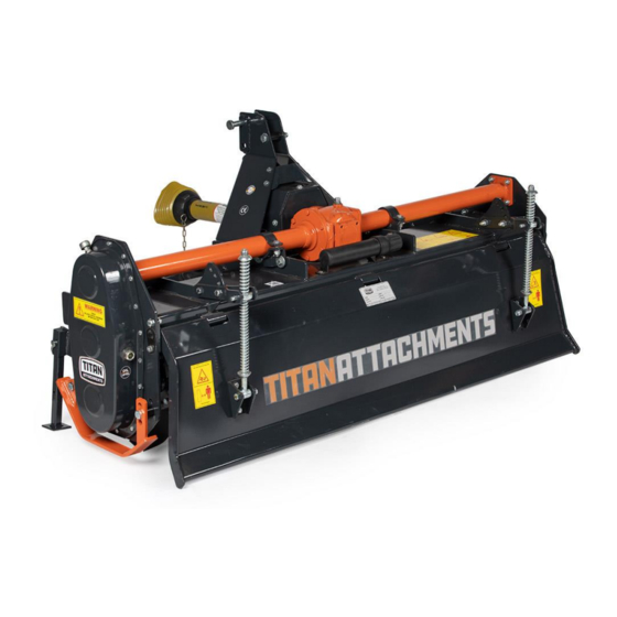
- Page 1 3 POINT ROTARY TILLER ROTIL48, ROTIL60, ROTIL72 191630,191631,191632 Operator’s Manual Read the Operator’s Manual entirely. When you see this symbol, the subsequent instructions and warnings are serious follow without exception. Your life and the lives of others depend on it!
-
Page 2: Intended Use
1. INTRODUCTION 1.1 TILLER IDENTIFICATION Each tiller has a plate for unique identification. Any request for assistance or information regarding the machine must be directed to the Manufacturer or Dealer always referring to the model and serial number as shown on the Serial Number Plate affixed to the machine. 1.2. -
Page 3: General Safety Instruction
2. SAFETY Careful operation is your best insurance against an accident. All operators, no matter how much experience they may have, should carefully read this manual and other related manual before operating the power machine and this implement. It is the owner’s obligation to instruct all operators in safe operation. -
Page 4: Operating Safety Instructions
• Before using the machine, familiarize yourself with its controls and its working capacity. • Do not leave the tiller unattended with tractor engine running. Shut off the power whenever going near the machine for repairing or lubrication purpose. • Do not use the machine if the category of the connecting pins of the tiller does not match that of the tractor hitch system. -
Page 5: Maintenance Safety Instructions
accidentally. • The implement may be wider than the tractor. Pay attention during transporting to persons, animals or obstacles exposed. • Always use tractor lighting system and auxiliary lighting system for an adequate warning to operators of other vehicles, especially when transporting at night or in conditions of reduced visibility. -
Page 6: Assembly And Setup
o Spray soapy water onto the cleaned area. o Peel backing from label and press label firmly onto the surface. o Squeeze out air bubbles with edge of a credit card or with a similar type of straight edge. 3. ASSEMBLYAND SET UP The Rotary Tiller is delivered fully assembled and equipped with a driveshaft with torque limiter (clutch discs) and related operating manual. - Page 7 3.2. 3-POINT LINKAGE ASSEMBLY 1. Attach TPL plate RHS (1) to the Main frame assembly with Hex head bolt M12x1.75x35 (11), Spring Washers (12) & Hex Nut (13). Do not tighten hardware at this time. 2. Repeat step-1 above to attach TPL Plate LHS (2) to Main Frame Assembly. 3.
-
Page 8: Connecting To The Tractor
3.3 CONNECTING TO THE TRACTOR Never stand between tractor and rotary tiller while backing up tractor to the hitch. • Place tiller and tractor on level ground. • Back tractor into position by lining up lift arms and Hitch bracket of the tiller linkage pins. Attach lift arms to linkage pins and secure with lynch pins. - Page 9 3.5 SIZING THE PTO SHAFT • Un-hook shaft from tractor PTO shaft and pull outer and inner shaft apart. • Reattach outer shaft to tractor PTO shaft. Pull on inner and outer shaft to be sure universal joints are properly secured. •...
- Page 10 to remove objects from the rotor bar until the tractor has been shut down and the tiller tines have completely stopped. 4.1 RAISING PARKING STAND 1. Remove spring locking pin. 2. Slide parking stand and way up on tiller bracket. 3.
- Page 11 When finished, verify that both skids are at same level, and check if the front of the tiller is leveled to the back, when lowered to the ground. Adjust with the 3-point top link if necessary. 4.3. REAR BOARD ADJUSTMENT The position of plank board is adjustable by varying the hole position on shocker mounting plate (A).
- Page 12 • Always keep oil and greases well away from children’s reach. Always thoroughly read the warnings and precautions indicated on the containers. • Avoid contact with the skin. • Always thoroughly and fully wash after use. The utilized oils should be treated in compliance with the current anti-pollution laws.
- Page 13 7. STORAGE 1. It is advisable to proceed in the following way at the end of the season or if the machine is to remain inactive for a long period of time: a. Wash the implement, particularly removing any fertilizer and/or chemical products, and then thoroughly dry it.
- Page 14 3. Solution — Change the P.T.O cross. a. Take the P.T.O shaft and check the cross of both side by rotating it. b. Remove the lock of the cross which is broken. c. Take out the cross by using hammer gently. d.
- Page 15 a. Open the top cover to see the wear of the teeth b. If the teeth of the gear is broken the bevel set needs to be replaced. c. Pull out the gear box and open the big flange. d. Then remove the back plate e.
- Page 16 THE SAME PROCESS BE FOLLOWED FOR DEAD SHAFT REPLACEMENT. 1. PROBLEM — OIL LEAKAGE FROM THE RD SHAFT HUB OR DEAD HUB. 2. Cause of problem — Seal is wearing out needs to replace it. 3. Solution — Open the hub assembly as before a.
-
Page 17: Torque Values Table
9. TORQUE VALUES TABLE... - Page 18 ROTARY CUTTER PARTS DIAGRAM / EXPLODED VIEW...
- Page 20 ROTARY CUTTER PARTS DIAGRAM / EXPLODED VIEW...
- Page 22 SIDE PLATE & ROTARY CUTTER PARTS DIAGRAM / EXPLODED VIEW...
- Page 24 GEAR BOX PARTS DIAGRAM / EXPLODED VIEW...
- Page 26 PTO SHAFT ASSEMBLY – SLIP CLUTCH TYPE...
-
Page 27: Slip Clutch Assembly
SLIP CLUTCH ASSEMBLY... - Page 28 ASSEMBLY INSTRUCTIONS − ROTARY TILLERS COME FULLY ASSEMBLED. ACKNOWLEDGEMENT OF RISK AND RELEASE OF LIABILITY The use of any equipment, including this one, involves the potential risk of injury. Apart from any warranty claim that might be presented for a claimed defect in material or workmanship of the product, you accept and assume full responsibility for any and all injuries, damages (both economic and non- economic), and losses of any type, which may occur, and you fully and forever release and discharge Titan, its insurers, employees, officers, directors, associates, and agents from any and all claims,...
- Page 29 NEED HELP? CONTACT US FIRST. 1-800-605-7595 info@palletworks.com www.palletforks.com © 2023 Titan Brands...
Need help?
Do you have a question about the ROTIL48 and is the answer not in the manual?
Questions and answers