Advertisement
Quick Links
Advertisement

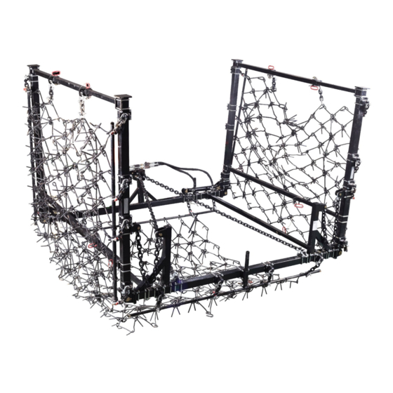
Summary of Contents for Titan Attachments HRWDRAWBAR8
- Page 1 OWNER’S MANUAL MPN(s): HRWDRAWBAR8 - HRWWINGKIT68 SKU(s): 191283 UPC(s): 840009220463...
- Page 2 PARTS DIAGRAM / EXPLODED VIEW – HDWRDRWBAR8 DESCRIPTION DESCRIPTION FLAT WASHER M10 (12) TELESCOPIC SIDE TUBE-1 TELESCOPIC SIDE TUBE-2 (13) PIN SHAFT ф16x80x6) LEG STAND MOUNTING BRACKET (14) LEG STAND ASSY COTTER PIN 4x70 (15) STEP PIN RING CAT1 TOP PIN (16) CAT1/2 STEP PIN LONG CHAIN...
- Page 3 PARTS DIAGRAM / EXPLODED VIEW DESCRIPTION HARROW TO DRAG BAR HARROW TO HARROW DRAG BAR...
- Page 4 ASSEMBLY INSTRUCTIONS SPECIAL NOTES: - The Wing Kit has left and right panels. Instruction below refers to a single panel only. - Build on flat and level ground. - Avoid tightening all hardware completely until the whole assembly is fully assembled. Step 1 –...
- Page 5 Step 5 – Secure HARROW DRAG TUBE onto Chain Assembly - Insert HARROW DRAG TUBE (11) through four Clevis hooks of SHORT CHAIN (18) at the front end of DRAWBAR MAIN FRAME (20), and four Clevis hooks of SHORT CHAIN (18) at the rear end of REAR DRAG BAR (9).
- Page 6 PARTS DIAGRAM / EXPLODED VIEW – HDWWINGKIT68...
- Page 7 DESCRIPTION DESCRIPTION DRAWBAR COUPLING TUBE (21) HINGE BRACKET - MALE U-BOLT (22) HINGE BRACKET - FEMALE CHAIN HOLDER-1 (23) PIN SHAFT-2 CHAIN ASSY-1 (24) GREASE ZERK M10x1 HARROW DRAG TUBE CLAMP (25) HEXA BOLT M10x35 HARROW DRAG TUBE (26) OIL HOSE - RETURN LYNCH PIN (27) OIL HOSE - FEED...
-
Page 8: Assembly Instruction
ASSEMBLY INSTRUCTION Special notes: - The Wing Kit is comprised of left and right wings. Instructions below refer to assembling the left wing only. After completion of left wing assembling, repeat the same steps for the right wing. - Build on flat and level ground. - Avoid tightening all hardware completely until the whole assembly is fully assembled. - Page 9 DESCRIPTION DESCRIPTION HARROW DRAWBAR ASSY RELIEF VALVE (22) (HRDWRBAR8) T-CONNECTOR (23) CYLINDER MOUNTING BRACKET-2 TELESCOPIC SIDE TUBE-BIG (24) CYLINDER HINGE BRACKET - MALE (25) OIL HOSE - RETURN HINGE BRACKET - FEMALE (26) CYLINDER MOUNTING BRACKET-1 STABLIZING CHAIN (27) OIL HOSE - FEED PIN SHAFT-1 (A20X70) (28) MAIN HOSE...
- Page 10 Step 1 – Attach front side of Left Wing to 3pt Harrow Drawbar (HRDWRBAR8) - Attach HINGE BRACKET – FEMALE (5) to the end of the Drawbar Frame of 3pt HARROW DRAWBAR ASSY (22) using HEXA BOLT M10x35 (30), FLAT WASHER M10 (32), SPRING WASHER M10 (33) and HEXA NUT M10 (34).
- Page 11 Step 8 – Mounting Cylinder onto the Wing/Drawbar Assembly - It is important to note that the piston rod of the cylinder must be pull to the longest extension during the assemble process. - With the full piston rod extension, adjust the position of the CYLINDER MOUNTING BRACKET-1 (26) on the Drawbar Frame of 3pt HARROW DRAWBAR ASSY (22) to match the cylinder mounting distance on the Wing and Drawbar Frame.
-
Page 12: Hydraulic System Diagram
HYDRAULIC SYSTEM DIAGRAM DESCRIPTION CYLINDER OIL HOSE - RETURN OIL HOSE - FEED HOSE CONNECTOR G0.375 RELIEF VALVE HOSE ADAPTOR (G1/4 TO G3/8) T-CONNECTOR HEXA THIN NUT G3-8 HOSE CONNECTOR MOUNTING BRACKET (10) SPRING WASHER M18 (11) MAIN HOSE (12) PIONEER COUPLER- MALE... - Page 13 This concludes the HRWDRAWBAR8 - HRWWINGKIT68 Owner’s Manual. If applicable to your product, make sure to tighten all nut-and-bolt combinations before use. Enjoy! DISCLAIMER This equipment must be used with care by capable and competent individuals under supervision, if necessary.


Need help?
Do you have a question about the HRWDRAWBAR8 and is the answer not in the manual?
Questions and answers