Table of Contents
Advertisement
Quick Links
Advertisement
Table of Contents

Related Manuals for Titan Attachments ADJDISCP2


Summary of Contents for Titan Attachments ADJDISCP2
- Page 1 ADJUSTABLE DISC PLOW ADJDISCP2, ADJDISCP3 191421, 191422 Operator’s Manual Read the Operator’s Manual entirely. When you see this symbol, the subsequent instructions and warnings are serious follow without exception. Your life and the lives of others depend on it!
- Page 2 USING THE INSTRUCTION MANUAL This handbook contains the use and maintenance instructions with a list of the spare parts of the implement. Regular and satisfactory operations together with economic and long-lasting use of the implement depend on the compliance with instructions given in this handbook. Compliance with the instructions in this handbook is also important since Manufacturer declines all and every responsibility for damage to persons or property caused by negligence and failure to comply with these instructions.
-
Page 3: Use Of The Implement
USE OF THE IMPLEMENT BEFORE USE: Before mounting of disc plough make sure that all nuts and bolts are properly secured. ATTACHING THE PLOUGH TO THE TRACTOR 1. Place the plough duly leveled on the flat piece of land. 2. Reverse the tractor to the plough (Do not drag the plough up the tractor) 3. - Page 4 WARNINGS The machine safety labels shown in this section are placed in important areas on your machine to draw attention to potential safety hazards. On your machine the words DANGER, WARNING and CAUTION are used with this safety-alert symbol. DANGER identifies the most serious hazards. The operator’s manual also explains any potential safety hazards whenever necessary.
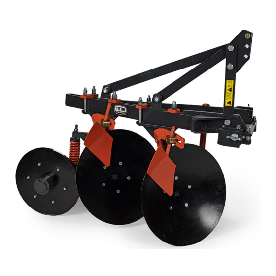
- Page 5 TECHNICAL DETAILS OF THE IMPLEMENT 1. Three – Point Hitch 2. Frame 3. Coulter Wheel 4. Disc 5. Drawbar 6. Scrapper...
- Page 6 To calculate the total weight of the implement, add together the weight of all the accessories to be mounted. Any accessory which does appear below is specific and so no weight as been given. MOVING THE IMPLEMENT To calculate the total weight of the implement, include the weight of any accessory.
- Page 7 Once you have obtained the desired depth. Check that the pins on the tractor and the pins on the plough are all equidistant from the ground. And the three-point hitch pin on the plough is approximately 1-5 cm higher than the three-point hitch-pin on the tractor. ADJUSTMENTS Before starting work with implement.
- Page 8 Note: Be careful not to overload the coulter wheel spring, which may cause penetration of the implement to be too shallow and cause the tractor to slip. 7. ADJUSTING THE VERTICAL POSITION OF THE DISC DURING WORK: The purpose of this adjustment is to make sure that the disc penetrates the ground.
-
Page 10: Parking The Implement
PARKING THE IMPLEMENT Perform the following operations when parking/storing the implement: 1. Select a firm, flat area. 2. Place the implement, which is still hitched to the tractor, on the ground. 3. Switch off the engine, apply the parking brake, remove the keys, and release the pressure in the hydraulic lines, if any, by manipulating the control lever(s) a few times. -
Page 11: Troubleshoot
TROUBLESHOOT... -
Page 13: Scheduled Maintenance
MAINTENANCE OF THE IMPLEMENT ALWAYS USE GENUINE SPARE PARTS. The manufacture is not liable for breakage, malfunctions, and injuries to people or damage to objects if genuine parts are not used. PREPARING THE IMPLEMENT FOR MAINTENANCE PERFORM THE FOLLOWING FOR ALL MAINTENANCE, ADJUSTMENT OF WORN PARTS, OR OTHER MANUAL SERVICE PERFORMED ON THE IMPLEMENT. -
Page 14: Parts Catalogue
PARTS CATALOGUE SPARE PARTS LIST WITH ASSEMBLY INSTRUCTION ORDERING SPARE PARTS You must provide the following information when ordering spare parts: • Serial number of the implement. • Name of implement. • Year of manufacture. • Part reference number. • Name of the Part. •... - Page 15 PARTS DIAGRAM / EXPLODED VIEW...
- Page 17 3-POINT LINKAGE ASSEMBLY...
- Page 18 COULTER SQUARE ROD ASSEMBLY...
- Page 19 COULTER HUB ASSEMBLY...
-
Page 20: Spindle Assembly
SPINDLE ASSEMBLY... -
Page 21: Demolition And Disposal
DEMOLITION AND DISPOSAL Its operation is to be carried out by the customer. Before demolishing the machine, you are advised to carefully check its physical condition and ascertain whether there are any parts of the structure that may be susceptible to structural collapse or breaking during demolition. - Page 22 ACKNOWLEDGEMENT OF RISK AND RELEASE OF LIABILITY The use of any equipment, including this one, involves the potential risk of injury. Apart from any warranty claim that might be presented for a claimed defect in material or workmanship of the product, you accept and assume full responsibility for any and all injuries, damages (both economic and non- economic), and losses of any type, which may occur, and you fully and forever release and discharge Titan, its insurers, employees, officers, directors, associates, and agents from any and all claims,...
- Page 23 NEED HELP? CONTACT US FIRST. 1-800-605-7595 info@palletworks.com www.palletforks.com © 2021 Titan Brands...
Need help?
Do you have a question about the ADJDISCP2 and is the answer not in the manual?
Questions and answers