
Subscribe to Our Youtube Channel
Related Manuals for Azbil FloWing VFR


Summary of Contents for Azbil FloWing VFR
- Page 1 FloWing Eccentric Rotary type Control Valves Model: VFR (6-inch or more) User’s Manual OM2-8130-0200 7th edition...
- Page 2 In no event shall Azbil Corporation be liable to anyone for any indirect, special or consequential damages. This information and specifications in this document are subject to change without notice.
-
Page 3: Table Of Contents
Table of Contents Chapter 1 : Installation 1-1 : Confirming the specifications ..............1-1 Compliance with Regulations ................1-1 Requirements for workers (installation, operation, maintenance) ...... 1-1 1-2 : Installation on piping .................. 1-2 1-3 : Inspecting and maintaining the installed valve ........1-3 Chapter 2 : Valve Body 2-1 : Description .................... - Page 4 Table of Contents Chapter 4 : Valve Positioner 4-1 : Smart Valve Positioner (SVP) ..............4-1 4-1-1 : Description ......................... 4-1 4-1-2 : Removing and installing the positioner ..............4-1 Removal ......................4-1 Installation ......................4-2 4-1-3 : Adjusting the positioner ....................4-2 4-1-4 : Maintaining the positioner ..................
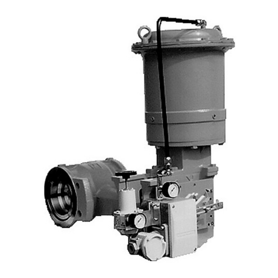
- Page 5 Azbil Corporation General The model VFR control valve consists of three main sections, namely, a valve body, a pneumatic actuator, and a valve positioner. The valve body is of an eccentric rotary type, which features large valve capacity and high operation stability. It is possible to use this valve for slurry service.
- Page 6 Azbil Corporation Model VFR - FloWing Eccentric Rotary type Control Valves...
-
Page 7: Chapter 1 : Installation
Azbil Corporation Installation Chapter 1 : Installation 1-1 : Confirming the specifications Prior to installing the valve, check that the model number, size, rating, materials and other specifications indicated on the nameplate attached on the actuator conform with those which were ordered. -
Page 8: Installation On Piping
Installation Azbil Corporation 1-2 : Installation on piping (1) Before installing the valve, remove scale, welding chips and other foreign material from both the upstream and downstream sides of the piping. (2) Pass the longer bolts through the lower half of the flanges to make up a cradle for the valve and place the valve on the cradle. -
Page 9: Inspecting And Maintaining The Installed Valve
Azbil Corporation Installation 1-3 : Inspecting and maintaining the installed valve Follow the procedures given below when inspecting or servicing an installed valve. (1) Verify that there is no leak from the air piping. (2) Verify that there are no loose clamping-bolts or nuts on the diaphragm case. - Page 10 Installation Azbil Corporation Model VFR - FloWing Eccentric Rotary type Control Valves...
-
Page 11: Chapter 2 : Valve Body
Azbil Corporation Valve Body Chapter 2 : Valve Body 2-1 : Description Figure 2-1 shows a cutaway view of the valve body section of the model VFR eccentric rotary valve. The valve body section consists of a valve body and a bonnet constructed as a single unit, and of a valve plug, a seat ring, and other trim parts. - Page 12 Valve Body Azbil Corporation Valve body Sheet retainer Sheet ring Blind plug * Packing ange Valve stem Stud bolt Plain bearing Spring ** Vale plug Packing ring Packing follower Main bushing Packing Figure 2-2 Cross sections *: For a valve without lubricator **: For a valve with lubricator, this space must be filled with packing instead of the spring.
-
Page 13: Disassembly
Azbil Corporation Valve Body 2-2 : Disassembly For the disassembly of the valve body section, dismantle the actuator observing the disassembly instructions described in “Chapter 3 : Actuator” and then proceed as follows: (1) Remove the clamping-bolts from the packing flange. -
Page 14: Assembly
Valve Body Azbil Corporation 2-3 : Assembly (1) Inset the valve plug into the valve body and press it against the plain bearing. (2) Insert the valve stem into the main bushing and insert the key in the key slot of the valve stem. - Page 15 Azbil Corporation Valve Body (6) Turn the valve stem so that the valve plug presses against the seat ring, then tighten the seat retainer with the seat ring remover-clamper. Packing ring Packing Blind plug Packing follower Packing ange Spring Without lubricator...
- Page 16 Valve Body Azbil Corporation Model VFR - FloWing Eccentric Rotary type Control Valves...
-
Page 17: Chapter 3 : Actuator
Azbil Corporation Actuator Chapter 3 : Actuator 3-1 : Description The model VR Actuator is a pneumatic and spring type diaphragm motor designed specifically for rotary type control valves. It holds the valve plug in a position where the pneumatic force and pneumatic force are mutually balanced. -
Page 18: Adjusting The Actuator
Actuator Azbil Corporation 3-2 : Adjusting the actuator The actuator requires to be adjusted if its action starts to shift or after it has been overhauled. Before adjusting the actuator, turn the manual handwheel to the fully clockwise position as viewed from the direction indicator plate. (See Figure 3-14) (1) Connect the air piping to the actuator through a pressure regulator. -
Page 19: Removing Actuator From Valve Body
Azbil Corporation Actuator 3-3 : Removing actuator from valve body (1) First, remove the positioner from the valve body referring to “Chapter 4 : Valve Positioner”. (2) After removing the positioner, remove the nut and then remove the cam and pointer from the valve stem end. -
Page 20: Disassembly Of Actuator
Actuator Azbil Corporation 3-4 : Disassembly of actuator To disassemble the actuator for parts replacement or servicing, follow the procedure described below. (See Figure 3-5.) When disassembling the actuator, take care not to damage the diaphragm or piston. (1) Loosen then remove uniformly the bolts and nuts of the diaphragm case (top). - Page 21 Azbil Corporation Actuator (5) Apply a wrench to the hex section of the actuator stem which has been pulled out and turn the spring compression nut counterclockwise to relieve the compression force of the spring. Then, remove the spring. Figure 3-7 ...
-
Page 22: Assembly Of Actuator
Actuator Azbil Corporation 3-5 : Assembly of actuator Since the mounting positions of parts differ depending on whether the valve is for direct action or reverse action, confirm the valve action by referring to the nameplate prior to assembling the actuator. -
Page 23: Mounting Actuator On Valve Body
Azbil Corporation Actuator Figure 3-11 (2) Place the assembled spring unit into the case following, in the reverse order, steps (4) and (5) in subsection “3-4 : Disassembly of actuator”. In this case, do not hold the assembly by its diaphragm. (See Figure 3-10.) (3) Fold the cup-shaped diaphragm into the case using a soft plate and pay attention not to scratch the diaphragm. -
Page 24: Manual Device (Handwheel)
Actuator Azbil Corporation 3-7 : Manual device (Handwheel) The manual device of the actuator can function as a limit stopper as well as its function as a conventional manual control device for the valve. E-clip Handwheel lock Handwheel shaft Handwheel Direction indicator Figure 3-14 ... -
Page 25: Setting Manual Control
Azbil Corporation Actuator 3-7-2 : Setting manual control First, switch the bypass cock (See Figure 4-9) of the posiitoner to the “ON” position. If the handwheel lock is released and the handwheel is rotated counterclockwise as viewed down towards the direction indicator plate, the valve will close if it is a direct action type or it will open if it is a reverse action type. - Page 26 Actuator Azbil Corporation 3-10 Model VFR - FloWing Eccentric Rotary type Control Valves...
-
Page 27: Chapter 4 : Valve Positioner
Azbil Corporation Valve Positioner Chapter 4 : Valve Positioner 4-1 : Smart Valve Positioner (SVP) 4-1-1 : Description The SVP (Smart Valve Positioner) is an intelligent valve positioner that can be connected to a 4-20 mA controller output signal line. Since all adjustments can be performed electrically, the relationship between the input signal and the position of the control valve can be set arbitrarily. -
Page 28: Installation
Valve Positioner Azbil Corporation Installation (1) Install the spacer onto the bracket. (2) Install the connector-plate onto bracket with feedback-pin. Since the position of spacer’s pin changes by flow direction, attach with reference to Figure 4-2 and Figure 4-3. (3) Tighten the clamping-bolt (M10, hex-hole-head) and attach the indicator to the connector-plate, and then tighten the clamping-bolt (M12, hex-hole head) and attach the pointer and mounting-plate. -
Page 29: Pneumatic Valve Positioner (Model Vfr)
Azbil Corporation Valve Positioner 4-2 : Pneumatic valve positioner (model VFR) 4-2-1 : Description The valve positioner is mounted on the model VR actuator and has the function of positioning the valve plug accurately and rapidly to a position corresponding to the pneumatic signal received from the controller. -
Page 30: Operating Principle
Valve Positioner Azbil Corporation 4-2-2 : Operating principle The valve positioner employs a force balance mechanism. See Figure 4-7 and Figure 4-8 for its operating principle. Nozzle back pressure Output pressure Valve opening Force Input Nozzle Pilot VR type Valve... -
Page 31: Bypass Cock
Azbil Corporation Valve Positioner 4-2-3 : Bypass cock Function of bypass cock The supply air bypass cock mechanism is provided on the bottom of the valve positioner. It is used to switch between the “ON” for “operation with positioner” and “SUP”... -
Page 32: Selecting Cam Characteristics
Valve Positioner Azbil Corporation 4-2-4 : Selecting cam characteristics To change valve characteristics Select a proper cam and install it. (For installation and adjustment procedures, refer to the respective sections.) Cam characteristics A single sheet of cam for the positioner can satisfy either linear characteristics or equal-percent characteristics. -
Page 33: Removing And Installing The Positioner
Azbil Corporation Valve Positioner 4-2-5 : Removing and installing the positioner Removal (1) Disconnect the air piping from the positioner. (2) Loosen the two clamping-bolts (M5, hex-hole head) with a hex wrench (4 mm) and remove the positioner cover. (See Figure 4-13.) (3) Loosen the two inner clamping-bolts (M6. - Page 34 Valve Positioner Azbil Corporation Figure 4-15 Types of actuator actions (b) Install the indicator and cam onto the male-threaded section of the cam holder. (c) Select a setting hole of the cam that corresponds to the actuator action and cam characteristics referring to Figure 4-16 and set the selected hole onto the boss of the indicator.
- Page 35 Azbil Corporation Valve Positioner (e) Release the air pressure applied to the actuator and disconnect the air piping. Figure 4-17 Installation of indicator and cam (for direct action and linear characteristics) (3) Installing the positioner (a) Loosen the two clamping-bolts (M5, hex-hole head) with a hex wrench (4 mm) and remove the positioner cover.
-
Page 36: Adjusting The Positioner
Valve Positioner Azbil Corporation 4-2-6 : Adjusting the positioner The positioner installed on a valve has been factory adjusted before shipment. When it has been replaced, however, the newly installed positioner is required to be adjusted in the following procedure. -
Page 37: Maintaining The Positioner
Azbil Corporation Valve Positioner (6) Turn the zero adjustment knob so that the output pressure of the positioner becomes the upper limit of the actuator spring range. When this is done, the indicator should indicate “S”. (Example: If the actuator spring range is 98 - 200 kPa {1 - 2 kg/cm²}, set the output pressure of the positioner to 200 kPa {2 kg/cm²}.) - Page 38 Valve Positioner Azbil Corporation Figure 4-20 Disassembly of the pilot relay 4-12 Model VFR - FloWing Eccentric Rotary type Control Valves...
-
Page 39: Troubleshooting
1. Inspect the valve body and actuator occurs or actuator The deviation unit requires to be disassembled. Disassembly should ~Note desirably be done by an Azbil Corporation service agent. Disassembly by the customer is not recommended. Model VFR - FloWing Eccentric Rotary type Control Valves 4-13... - Page 40 Valve Positioner Azbil Corporation 4-14 Model VFR - FloWing Eccentric Rotary type Control Valves...
-
Page 41: Chapter 5 : Changing The Mounting Attitude Of Actuator And Type Of Valve Action
Azbil Corporation Changing the mounting attitude of actuator and type of valve action Chapter 5 : Changing the mounting attitude of actuator and type of valve action The mounting attitude of the model VFR valves actuator can be changed and the type of its action can be modified without requiring any additional parts. - Page 42 Azbil Corporation Changing the mounting attitude of actuator and type of valve action Figure 5-1 Mounting attitudes of the actuator Figure 5-2 For SVP Figure 5-3 For model VPR Figure 5-4 Model VFR - FloWing Eccentric Rotary type Control Valves...
- Page 44 1. Warranty period and warranty scope 1.1 Warranty period Azbil Corporation's products shall be warranted for one (1) year from the date of your purchase of the said products or the delivery of the said products to a place designated by you.
- Page 45 Although acceleration of the above situation varies depending on the conditions or environment of use of the products, you are required not to use any Azbil Corporation's products for a period exceeding ten (10) years unless otherwise stated in specifications or instruction manuals.
- Page 47 Document Number: OM2-8130-0200 Document Name: FloWing Eccentric Rotary type Control Valves Model: VFR (6 in. or more) User’s Manual Date: 7th edition: Apr. 2023 Issued/Edited by: Azbil Corporation...
Need help?
Do you have a question about the FloWing VFR and is the answer not in the manual?
Questions and answers