Table of Contents
Advertisement
Quick Links
General
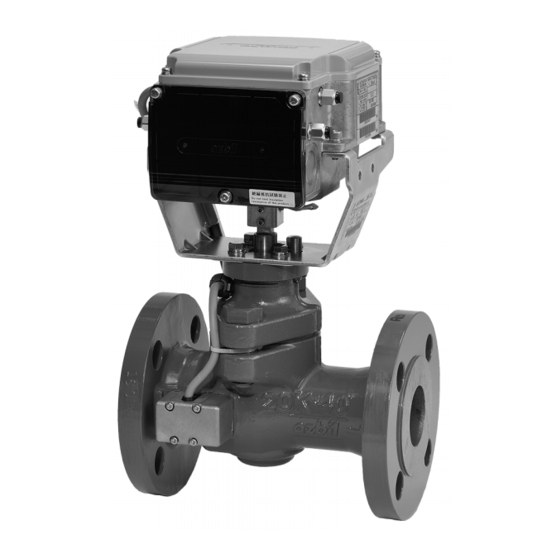
ACTIVAL + Model FVY513EJ/FVY514EJ is a series of
motorized two-way valves with flanged-end connection. Rotary
valve and actuator are integrated in a single unit.
Valve size ranges from DN15 (1/2") to DN80 (3"), and valve
body rating corresponds to JIS 20K.
In combination with the functions of a control valve, Model
FVY513EJ/FVY514EJ measures and controls flow. Model
FVY513EJ/FVY514EJ thus enables to control temperature for
air conditioning by controlling chilled/hot water volume and to
measure chilled/hot water flow.
For such a high functionality, compact size and simple
installation of Model FVY513EJ/FVY514EJ are incomparable.
2 kinds of control signals are available to operate the Model
FVY513EJ/FVY514EJ.
- 4-20 mA DC input:
Provides proportional control in combination with a DDC
controller. (e.g., Infilex
R35/R36)
- 2-10 V DC input:
Provides proportional control in combination with a DDC controller. (e.g., Infilex
Flow data stored in Model FVY513EJ/FVY514EJ is retrieved via RS-485 communication (Modbus protocol). The retrieved flow
data is effective for energy-saving facility operation.
* JIS: Japanese Industrial Standards
* DDC: Direct Digital Control
Features
Compact and lightweight:
Rotary valve actualizes small body and light weight.
Valve and actuator integrated in a single unit.
Model FVY513EJ/FVY514EJ holds flow data effective
for maintenance and energy-saving facility operation.
The data is retrieved via RS-485 communication
(Modbus protocol).
Valve for chilled/hot water control applicable to large Cv
value, high rangeability, and low leakage.
Durable actuator with low power consumption.
IMPORTANT:
Do not use the data measured by this product for charging or dealing purposes.
Standalone Model
(JIS 20K / SCPH2)
GC Model WY5111, Model
AC Model WY5117)
Flow rate control/position control operation selectable:
For flow rate control, flow characteristic is selectable
(equal percentage or linear). For position control, flow
characteristic is equal percentage.
In combination with the optional Display Panel (Model
QY5010S1000) and the insertion-type pipe temperature
sensor (Model TY7830) or the temperature sensor for
pipe surface (Model TY7820), pressure, temperature,
and flow can be displayed on the Display Panel.
© 2012–2020 Azbil Corporation. All Rights Reserved.
1
AB-7131
Specifications/Instructions
Advertisement
Table of Contents

Related Manuals for Azbil ACTIVAL+ FVY513E Series


Summary of Contents for Azbil ACTIVAL+ FVY513E Series
- Page 1 Display Panel. value, high rangeability, and low leakage. Durable actuator with low power consumption. IMPORTANT: Do not use the data measured by this product for charging or dealing purposes. © 2012–2020 Azbil Corporation. All Rights Reserved.
-
Page 2: Safety Instructions
Excessive tightening or improper installation where reliability or control accuracy is particularly required, position may damage the valve. please contact our sales representative. Azbil Corporation After installation, make sure no fluid leaks from the will not bear any responsibility for the results produced by valve-pipe connections. -
Page 3: Model Numbers
AB-7131 IMPORTANT: This product is applicable only to chilled/hot water control. If the product is used to control any other medium such as brine or air, flow rate cannot be measured or controlled. Install the valve so that the flow direction of process fluid agrees with the arrow indicated on the valve body. If the flow direction is opposite to the arrow, correct measurement and control of flow is not assured. - Page 4 AB-7131 Options Separately order the following optional parts if needed. Item Specification Note Seal connector is necessary for IEC IP54 7 mm to 9 mm Seal connector Part No. protection. 83104346-003 9 mm to 11 mm Part No. 83104346-004 11 mm to 13 mm Part No.
-
Page 5: Valve Specifications
AB-7131 Specifications For weight, refer to the table shown in the section Dimensions. Valve and actuator (as a single unit) specifications Item Specification -20 C to 50 C Environmental Rated operating conditions Ambient temperature conditions (Do not allow the process fluid to freeze.) Ambient humidity 5 %RH to 95 %RH Vibration... -
Page 6: Actuator Specifications
AB-7131 Actuator specifications Item Specification 24 V AC 15 %, 50 Hz/60 Hz Power supply Applicable valve type DN15 to DN80, standard torque Power consumption 8 VA 63 5 sec (50 Hz) / 53 5 sec (60 Hz) Timing Control signal Model FVY513EJ... -
Page 7: Measuring Range And Accuracy
AB-7131 Measuring range and accuracy (1/2) Item Specification Model number Nominal size Cv value Max. set flow rate Flow rate measuring Setting range FVY513EJ0012 / FVY514EJ0012 DN15 (1/2”) 25 l/min FVY513EJ0013 / FVY514EJ0013 DN15 (1/2”) 60 l/min FVY513EJ0021 / FVY514EJ0021 DN25 (1”) 100 l/min FVY513EJ0022 / FVY514EJ0022... - Page 8 AB-7131 (2/2) Item Specification Pressure Measuring 0 MPa to 2.0 MPa* measuring range 0.5 %FS (factory preset)* Accuracy of the displayed pressure 0 C to 80 C Temperature Measuring measuring range 1.0 C (factory preset)* Accuracy (within 0 C to 80 C measuring range, at -25 C to 40 C temperature difference between measuring temperature and ambient temperature) Conversion accuracy: ...
-
Page 9: Wire Specifications
AB-7131 Wire Specifications Item Specification Length* Connection Power JIS CVV, JIS IV M3.5 screw connection 0.75 mm , 1.25 mm , 2.0 mm ® Control signal, DI (Cooling/heating switch JIS CVV, JIS IV, KPEV , JCS* CVV-S 50 m M3.5 screw connection signal), pulse output 0.75 mm... -
Page 10: Parts Indication
AB-7131 Parts Indication Valve details Top cover Top cover Terminal cover Actuator Knockout Terminal cover Yoke Pointer Gland packing Joint Bonnet Stem Seat ring Valve body Plug : Heat insulation Figure 2. Parts Indication: Valve details Actuator details (Connectors, ports, terminals and LED) Connector for Pt100 input Reset switch Row T1: Supply water temperature... -
Page 11: Notes For Installation
AB-7131 Installation WARNING When handling or transporting any heavy product (more than 18 kg), carefully move the product with a hand truck or the like, or with 2 or more people. Careless lifting or accidental dropping of the product may result in injury or product damage. ... -
Page 12: Mounting Position
AB-7131 Mounting position Install the valve so that fluid flows in the direction pointed by the arrow on the valve body, and keep the valve orientation as described below. Orientation of the actuator cannot be changed. The product can be mounted with any position from upright to sideways (max. 90-degree inclination) and flow direction is from bottom to top. - Page 13 AB-7131 3) Fully open the valve and flush it out with the maximum flow rate. When fluid flows for the first time, it is to clean out the foreign substances and refuse in the pipes. The valve is set to fully open when it is shipped from the factory. ...
- Page 14 AB-7131 Manually opening/closing valve IMPORTANT: Before opening or closing the valve manually, turn off the power. If the valve is manually opened or closed while the power 24 V AC active, the actuator may break down. Do not manually open or close the valve more than 100 % or less than 0 % scale. 1) Turn off the power.
-
Page 15: Wiring Procedure
AB-7131 Wiring CAUTION Provide a circuit protector (e.g., a fuse or circuit breaker) for the power source. Failure to do so may cause a short circuit leading to fire or device failure. Install, wire, and use this product under the conditions specified by this manual. ... - Page 16 AB-7131 3) Refer to Figs. 3 and 10 and correctly connect the wires to the M3.5 screw terminals. Note that the wires of the temperature sensor, Display Panel, and RS-485 communication lines are connected to the connectors. Control signal (Cooling/heating 24 V AC cable Pulse output switch signal)
- Page 17 AB-7131 3) Unplug the 6-pin connector for temperature sensor (Pt100 input) from the actuator socket, and connect the sheath stripped wires (3-core cable of the temperature sensor (Pt100 input)) to the connector. Insert a slotted screwdriver (with 2.5 0.4 mm blade tip) into a square hole of the connector for clamp release. The screwdriver successfully releasing the clamp remains the inserted position.
-
Page 18: Precautions For Connection
AB-7131 3) Unplug the 6-pin connector for RS-485 communication from the actuator socket, and connect the sheath stripped wires to the connector. Insert a slotted screwdriver (with 2.5 0.4 mm blade tip) into a pocket on the top/bottom of the connector for clamp release. - Page 19 AB-7131 Internal isolation: Only the pulse output and the RS-485 communication are internally isolated. Isolator therefore is required to connect a non-isolated device to the control signal input and DI (Cooling/heating switch signal) of the product. Solid line: Isolated, Dashed line: Not isolated Power T1 (Supply water temperature) T2 (Return water temperature)
-
Page 20: Connection Examples
AB-7131 Connection examples Controller Isolator* (e.g. Model R35/R36TC0) Isolator* Controller Model FVY513EJ Model FVY513EJ (e.g. Model R35/R36TC0) (4-20 mA input) (4-20 mA input) Isolator* Isolator* Controller Power Power Model FVY513EJ Model FVY513EJ Power (e.g. Model R35/R36TC0) (4-20 mA input) (4-20 mA input) Notes: Notes:... - Page 21 AB-7131 Slave (Model R series) Master Slave (Model FVY51XEJ: this product) Figure 26. Connection example: 3-wire RS-485 communication Slave (Model R series) Master Note: This product has 3-wire communication line connection. The example shows 5-wire communication line connection of the master device. Slave (Model FVY51XEJ: this product) Figure 27.
- Page 22 AB-7131 Cable Gland with Three Ports Cable gland with three ports (Model DY7000A1000) is recommended to attach to a wiring port (knockout) of this product when RS-485 communication line and signal line are passed through the same wiring port. The cable gland with three ports is applicable to cables for small power.
- Page 23 AB-7131 Connecting the cable gland with three ports Refer to the below table and tighten each part of the cable gland to connect it onto a wiring port (knockout) of this product. Part of cable gland with three ports Fastening torque 1.8 Nm ...
- Page 24 AB-7131 5) Loosen the cap of a seal connector. Let the wires through the seal connector so that the end of the sheath comes to inner side of the cover. Then, tighten the cap of the seal connector to fix the cable. Cables Seal connectors Wires (sheath stripped part)
- Page 25 AB-7131 Detaching the cable gland with three ports 1) Disconnect the cables (wires) connected to the terminals/connectors of the product. 2) Release the 3 latches that assemble the cover and base of the cable gland. If the cable fixing position near the product disturbs removal of the cover from the base, unfix the cable position (untie the cable tie).
-
Page 26: Maintenance
AB-7131 Maintenance CAUTION Do not put a load or weight on this product. Doing so may damage the product. Before doing maintenance, be sure to turn off the power to this product. Failure to do so may result in electric shock or device failure. After maintenance, be sure to reattach the cover. - Page 27 AB-7131 1 cm 1 cm Pointer Lower setscrew of the terminal cover Figure 35. Check of the valve position detecting accuracy Disposal Dispose of this product as industrial waste in accordance with your local regulations. Do not reuse all or any part of the product.
- Page 28 AB-7131 ACTIVAL and ACTIVAL + are trademarks of Azbil Corporation in Japan or in other countries. This product complies with the following Electromagnetic Compatibility (EMC). EMC: EN61000-6-2, EN55011 Class A Specifications are subject to change without notice. Building Systems Company...
Need help?
Do you have a question about the ACTIVAL+ FVY513E Series and is the answer not in the manual?
Questions and answers