Advertisement
Quick Links
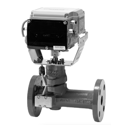
Motorized Two-Way Valve with Flanged-End Connection
„ General
ACTIVAL +
TM
Model FVY51_FJ is a series of motorized two-
way valves with flanged-end connection. Rotary valve and
actuator are integrated in a single unit.
In combination with the functions of a control valve, Model
FVY51_FJ measures and controls flow. Model FVY51_FJ
thus enables to control temperature for air conditioning by
controlling chilled/hot water volume and to measure chilled/
hot water flow.
For such a high functionality, compact size and simple
installation of Model FVY51_FJ are incomparable.
Model FVY51_FJ is operated by the following control signal.
1. 4–20 mA DC input
2. 2 to 10 V input
Both provide proportional control in combination with a
single loop controller (e.g., Model SDC35/SDC36)
Flow data stored in Model FVY51_FJ is retrieved via RS-485
communication (Modbus protocol). The retrieved flow data is
effective for energy-saving facility operation.
„ Features
Compact and lightweight:
•
Rotary valve actualizes small body and light weight.
Valve and actuator integrated in a single unit.
•
NEMA 4X and IP54 enclosure rating
•
(Waterproof connectors are required to assure NEMA 4X
and IP54)
Valve for chilled/hot water control applicable to large Cv
•
value, high rangeability, and low leakage.
Durable actuator with low power consumption.
•
Flow control/position control operation selectable:
•
For flow control, flow characteristic is selectable
(equal percentage or linear). For position control, flow
characteristic is equal percentage.
IMPORTANT:
Do not use the data measured by this product for charging or dealing purposes.
Standalone Model
(ANSI Class 125 / A126 Class B)
M o d e l F V Y 5 1 _ F J h o l d s f l o w d a t a e ff e c t i v e f o r
•
maintenance and energy-saving facility operation. The
data is retrieved via RS-485 communication (Modbus
protocol).
In combination with the optional Display Panel (Model
•
QY5010S2000) and the insertion-type temperature
sensor (Model TY7830) or the temperature sensor for
pipe surface (Model TY7820), pressure, temperature,
and flow can be displayed on the Display Panel.
Note: The display panel, the insertion-type pipe temperature
sensor, and the temperature sensor for pipe surface should be
ordered separately.
© 2018 Azbil Corporation All Rights Reserved.
1
AB-7487-U
Specifications/Instructions
Advertisement

Subscribe to Our Youtube Channel
Related Manuals for Azbil ACTIVAL+ FVY51 FJ Series


Summary of Contents for Azbil ACTIVAL+ FVY51 FJ Series
- Page 1 For flow control, flow characteristic is selectable (equal percentage or linear). For position control, flow characteristic is equal percentage. IMPORTANT: Do not use the data measured by this product for charging or dealing purposes. © 2018 Azbil Corporation All Rights Reserved.
-
Page 2: Safety Precautions
Azbil Corporation. like, or with 2 or more people. Azbil Corporation bears no responsibility for any Careless lifting or accidental dropping of the result, or lack of result, deriving from the product may result in injury or product customer’s use of the product. - Page 3 IMPORTANT: In case an Azbil Corporation product fails, you are required to provide your Equipment with safety design such as fool-proof design* , and fail-safe design* (anti-flame propagation design, etc.), whereby preventing...
- Page 4 AB-7487-U IMPORTANT: • Install the product to a pipe so that they are electrically connected at the same potential. If the valve and the pipe are electrically isolated, noise might be generated, causing incorrect measurement and control of flow. • When installing the product with flange gasket, do not use the rubber gasket or the gasket that goes inside the pipe.
- Page 5 AB-7487-U „ Model Numbers Model FVY51_FJ is the model for the valve and actuator integrated into a single unit. The model number label is attached to the yoke. Actuator / Valve Actuator Valve Base model Generation Description Control Rating / Nominal Type Fixed...
- Page 6 AB-7487-U Valve specifications Item Specification Model Two-way valve with flanged-end connection Body pressure rating ANSI Class 125 End connection ANSI Class 125 bolt pattern flanges, flat face flange (FF) Size, Cv, Close-off ratings Model number Nominal size Close-off ratings Inch FVY51_FJ0021 1"...
- Page 7 AB-7487-U Actuator specifications Item Specification Power supply 24 V AC± 15 %, 50 Hz/60 Hz Power consumption 8 VA Timing 63 ± 5 sec (50 Hz) / 53 ± 5 sec (60 Hz) Control signal Model FVY513 4 to 20 mA DC input (Input impedance: 250 Ω) Model FVY514 2 to 10 V DC input (Input impedance: 500 kΩ) Input type...
- Page 8 AB-7487-U Measuring range and accuracy IMPORTANT: Flow measuring accuracy shown in the below is for the valve sensor measuring 44.6 to 62.6 °F (7 to 17 °C) and 113 to149 °F (45 to 65 °C) ranges, 29 to 261 psi pipe pressure, and 4.35 to 43.5 psi diff erential pressure.
- Page 9 AB-7487-U „ Data in Model FVY51_FJ Flow data Following items are displayed on Display Panel (Model QY5010S2000): Actual flow, supply water temperature, return water temperature, valve inlet pressure, valve outlet pressure, actual flow (% in bar graph), actual valve position (% in bar graph) Following items are retrieved via RS-485 communication (Modbus protocol): Control setting value, actual valve position, actual flow, set flow, supply water temperature, return water temperature, valve inlet pressure, valve outlet pressure, instantaneous energy, totalized flow,...
- Page 10 AB-7487-U „ Dimensions 2.76” (70mm) 2.76” (70mm) 3.23" (82mm) 3.35" (85mm) Flow direction indication N × h Dia. Valve sensor cable Valve sensor (in valve sensor cover) Model number Valve size L (in) L1 (in) H (in) H1 (in) D (in) C (in) t (in) φh (in)
- Page 11 AB-7487-U Actuator details (Connectors, ports, terminals, and LED) Connector for Pt100 input Reset switch Row T1: Supply water temperature Connector for Connector for Row T2: Return water temperature RS-485 communication Display Panel Operating status LED (red) Port for Port for valve sensor cable Display Panel cable Port for...
- Page 12 AB-7487-U „ Installation Precautions for installation WARNING When handling or transporting any heavy product (more than 39.7 lb (18 kg)), carefully move the product with a handtruck or the like, or with 2 or more people. Careless lifting or accidental dropping of the product may result in injury or product damage. ...
- Page 13 AB-7487-U Installation location IMPORTANT: • The top and the terminal covers might be corroded by chemicals and organic solvent or their vapor. Do not expose the product to such substances/vapor. • Although the product can be used in high humidity environments (max. 95 % RH), do not immerse the actuator in water.
- Page 14 AB-7487-U Mounting position Model FVY51_FJ can be mounted in any position ranging from upright to sideways (90° tilted). Note that Model FVY51_FJ must be installed with the valve sensor vertically positioned above the valve body when being tilted. It is also installable on the vertical upflow pipe.
- Page 15 AB-7487-U Piping CAUTION When installing this product, hold it in the proper position and securely fasten it to the pipes. Excessive tightening or improper installation position may damage the valve. IMPORTANT: Do not put force on the valve sensor or its cable to prevent failure. •...
- Page 16 AB-7487-U Manually opening/closing Model FVY51_FJ IMPORTANT: • Manually opening/closing the product with the power (24 V AC) applied might damage the actuator. • To manually open/close the product, do not turn the joint beyond the fully open (100)/closed (0) mark. •...
- Page 17 AB-7487-U „ Wiring CAUTION Provide a circuit protector (e.g., a fuse or circuit breaker) for the power source. Failure to do so may cause a short circuit leading to fire or device failure. Install, wire, and use this product under the conditions specified by this manual. ...
- Page 18 AB-7487-U Wiring procedure 1) To lead the wires into the terminals, open a knockout for a wiring port. Two knockouts are provided on the bilateral sides of the actuator terminals. Select a knockout according to the conduit mounting direction, and open the hole by lightly knocking the knockout using a screwdriver.
- Page 19 AB-7487-U 6) Tighten the seal connectors of the wiring ports. On the wiring ports for Display Panel cable and temperature sensor (Pt100 input) cable, tighten the seal connectors until the clearance between the wiring port and the seal connector becomes narrower than 0.04"...
- Page 20 AB-7487-U 4) Plug the connector into the actuator socket. Note: Completely plug the connector into the actuator socket. Incompletely plugged connector might become unplugged due to vibration. Wires connection of Display Panel Terminal Wire color* Description R B W R: RED 12 V DC B: BLK...
- Page 21 AB-7487-U 4) Plug the connector into the actuator socket. Note: Completely plug the connector into the actuator socket. Incompletely plugged connector might become unplugged due to vibration. Wires connection of control signal, DI (Cooling/heating switch signal), pulse output 1) Pass the cable of control signal/DI/pulse output through a wiring port on the other side of the port for power supply cable. 2) Use 4- or 6-core cable for connecting the wires of the multiple signal lines.
- Page 22 AB-7487-U Single controller with multiple 4 to 20 mA input type products (See Figs. 22 and 23.): 4 to 20 mA control signal input is not isolated from the power, and the 4 to 20 mA input impedance is 250 Ω. For connecting a controller, the relations among the input impedance of this product, the output load resistance of the controller, and the output load resistance and input impedance of an isolator (if necessary) must meet the following formula.
- Page 23 AB-7487-U Controller (e.g. Model SDC35/ Isolator* SDC36TC0) Model FVY513FJ Isolator* Controller Model FVY514FJ (4 to 20 mA input) (e.g. Model SDC35/ (2-10 V input) SDC36TD0) Isolator Power Model FVY513FJ (required) (4 to 20 mA input) Power Isolator* Model FVY514FJ (2-10 V input) Notes: *1 Provide an isolator for the controller not internally isolated.
- Page 24 AB-7487-U Shielded Slave (Model SDC series) Master Shielded Note: * This product has 3-wire communication line connection. The example shows 5- wire communication line connection of the master device. Slave (Model FVY513FJ: this product) Figure 26. Connection example: 5-wire RS-485 communication Protection diode Magnetic counter Model FVY513FJ...
- Page 25 AB-7487-U „ Inspection and Troubleshooting CAUTION Do not put a load or weight on this product. Doing so may damage the product. Before doing maintenance, be sure to turn off the power to this product. Failure to do so may result in electric shock or device failure. After maintenance, be sure to reattach the terminal cover.
- Page 26 AB-7487-U 0.39" 0.39" (1 cm) (1 cm) Pointer Lower setscrew of the terminal cover Figure 29. Check of the valve position detecting accuracy „ Disposal Dispose of this product as industrial waste in accordance with your local regulations. Do not reuse all or any part of the product.
- Page 27 AB-7487-U This blank page was added for page layout purposes.
- Page 28 Electronic Equipment Directive (RoHSD). EMCD: EN 61000-6-2 EN 61000-6-4 RoHSD: EN 50581 ACTIVAL and ACTIVAL + are trademarks of Azbil Corporation in Japan or in other countries. 9033 N. 24th Ave., Suite 6 Phoenix, AZ 85021 888-262-4639 Building Systems Company...
Need help?
Do you have a question about the ACTIVAL+ FVY51 FJ Series and is the answer not in the manual?
Questions and answers