Advertisement
88564949 C
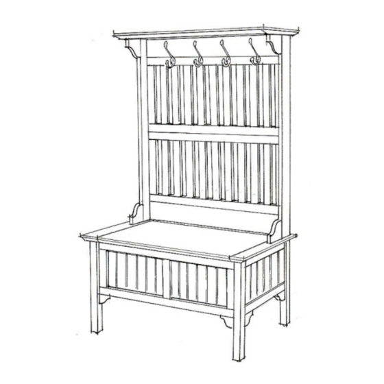
Hall Tree Storage Bench
Dear Our Valuable Customers,
Please follow our assembly instructions in every step,
we guarantee that you will get the perfect merchandise.
Thank you so much for purchasing our quality products.
BASE UNIT PART LIST
A.
Seat
1 pc.
D.
Front Panel
1 pc.
Hex Wrench
1 pc.
Tools Required For Assembly : Philips screwdriver
Side Panel
E.
Back Panel
1 pc.
Head Cap Bolt
(short)
4 pcs.(+ 1 Extra)
Head Cap Bolt
Cross Dowel
(long)
8 pcs.(+2 Extra)
8 pcs.(+1 Extra)
Thai Patent Pending Numbers 081316
B.
1 pc.
Spring Support
2 pcs.
C.
Side Panel
1 pc.
F.
Base
1 pc.
Wood Screw
(for Spring Support)
8 pcs.(+1 Extra)
Wood Plug
8 pcs. (+1 Extra)
Advertisement
Table of Contents

Related Manuals for Home Styles 88564949 C


Summary of Contents for Home Styles 88564949 C
- Page 1 88564949 C Hall Tree Storage Bench Dear Our Valuable Customers, Please follow our assembly instructions in every step, we guarantee that you will get the perfect merchandise. Thank you so much for purchasing our quality products. Thai Patent Pending Numbers 081316...
- Page 2 Assembly Instructions IMPORTANT Do not tighten up all the screws until each part is properly assembled. You should keep Hex Wrench in the safe place as you may need to tighten up the Head Cap Bolts in the future. Head Cap Bolt (long) Cross Dowel Cross Dowel...
- Page 3 88564949 C Hall Tree Storage Bench Dear Our Valuable Customers, Please follow our assembly instructions in every step, we guarantee that you will get the perfect merchandise. Thank you so much for purchasing our quality products. Thai Patent Pending Numbers 081316 TOP UNIT PART LIST 1 pc.
- Page 4 Assembly Instructions 2/3 IMPORTANT Do not tighten up all the screws until each part is properly assembled. You should keep Hex Wrench in the safe place as you may need to tighten up the Head Cap Bolts in the future. STEP 1 Hook Attach the Hooks to the Upper Back Frame (J)
- Page 5 Assembly Instructions 3/3 Head Cap Bolt (long) Head Cap Bolt (long) STEP 4 Attach the Top (G) to the Side Panel (H) and (I) with Head Cap Bolts as shown. Attach the Arm (M) and (N) to the Side Panels with Head Cap Bolts. STEP 5 Place the Top Unit on the Base Unit.
Need help?
Do you have a question about the 88564949 C and is the answer not in the manual?
Questions and answers