Advertisement
Quick Links
88 5542 182
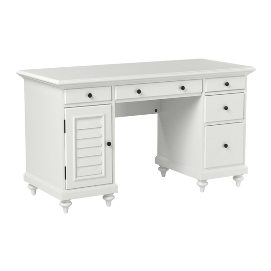
Bermuda
Pedestal Desk
IMPORTANT NOTE
Carefully remove all the parts from the carton and put
them individually on a soft cloth to prevent scratches
or other damage occuring to the parts.
We have taken great care in the design of this
product and request that you carefully and strictly
follow our assembly instructions to ensure a
completed product as it was designed.
Part List
B.
Side Panel
1 Pc.
F.
Front Rail
5 Pcs.
R.
Door
1 Pc.
Also need the Parts and Hardware in carton 88 5542 181
Tools required for assembly : Phillips screwdriver
C.
Side Panel
1 Pc.
S.
Drawer
2 Pcs.
(Knock-Down Construction, please refer to the last page of
these instructions for drawers assembly steps.)
Home Styles Consumer Assistance: www.homestyles-furniture.com,
servicedesk@homestyles-furniture.com, 888-680-7460, 877-831-0319
D.
Side Panel
1 Pc.
G.
Base
2 Pcs.
Q.
Leg
8 Pcs.
T.
Drawer
1 Pc.
Tools recommended for assembly : Level
E.
Side Panel
1 Pc.
U.
V.
Drawer
Metal Strip
1 Pc.
2 Pcs.
H.
Back Panel
2 Pcs.
Advertisement

Subscribe to Our Youtube Channel
Related Manuals for Home Styles Bermuda Pedestal Desk


Summary of Contents for Home Styles Bermuda Pedestal Desk
- Page 1 (Knock-Down Construction, please refer to the last page of these instructions for drawers assembly steps.) Also need the Parts and Hardware in carton 88 5542 181 Tools required for assembly : Phillips screwdriver Tools recommended for assembly : Level Home Styles Consumer Assistance: www.homestyles-furniture.com, servicedesk@homestyles-furniture.com, 888-680-7460, 877-831-0319...
- Page 2 Assembly Instructions 2 IMPORTANT * Please keep Hex Wrench in a safe place as you may need to tighten up the Head Cap Bolts in the future. * Do not tighten up all the screws until each part is properly assembled. * Use a soft cloth between these parts and the fl...
- Page 3 Assembly Instructions 3 Cam Lock Cam Lock Screw STEP 2 Attach Front Rails (F), Back Panel (H) and Base (G) to Side Panel (B) with Cam Locks. (see Figure 3) Attach Side Panel (C) to unit with Cam Locks. Figure 3 Attach Legs (Q) to Base (G).
- Page 4 Assembly Instructions 4 STEP 4 Insert Cam Lock Screws into the pre-drilled holes of Keyboard Supports (N) and (O). Attach Keyboard Supports (N) and (O) to Keyboard Support (P) with Cam Locks. Attach Keyboard Rails (M) to unit with Cam Lock Screws and Cam Locks. Head Cap Bolt Figure 4 STEP 5...
- Page 5 Assembly Instructions 5 STEP 6 Attach Top (A) to unit with Cam Locks. Attach Keyboard Front (K) to Keyboard (L) with Wood Screws for hinge. (see Figure 5) Slide keyboard into position. Wood Screw for hing Figure 5 Figure 6 Figure 7 Figure 8 STEP 7...
-
Page 6: Parts List
Assembly Instructions 6 /9 Keyboard (L) STEP 1 Attach L1 to L4, using a Phillips screwdriver and long wood screws (3X), tighten halfway. (see Figure 1) Figure 1 Figure 2 STEP 2 Attach L2 and L3 to unit, using a Phillips screwdriver and long woodscrews (8X), tighten halfway. - Page 7 Assembly Instructions 7 Drawer (S) STEP 1 Attach S1 to S3 and S4, using a Phillips screwdriver and long wood screws (4X), tighten halfway. Figure 1 Attach S2 to S3 and S4 using long wood screws (4X), tighten halfway. (see Figure 1) STEP 2 Slide S5 into the grooves in S3 and S4.
- Page 8 Assembly Instructions 8 Drawer (U) STEP 1 Attach U1 to U3 and U4, using a Phillips screwdriver and long wood screws (6X), tighten halfway. Figure 1 Attach U2 to U3 and U4 using long wood screws (6X), tighten halfway. (see Figure 1) STEP 2 Slide U5 into the grooves in U3 and U4.
- Page 9 Assembly Instructions 9 Drawer (T) STEP 1 Attach T1 to T3 and T4, using a Phillips screwdriver and long wood screws (4X), tighten halfway. Figure 1 Attach T2 to T3 and T4 using long wood screws (4X), tighten halfway. (see Figure 1) STEP 2 Slide T5 into the grooves in T3 and T4.
Need help?
Do you have a question about the Bermuda Pedestal Desk and is the answer not in the manual?
Questions and answers