Advertisement
Quick Links
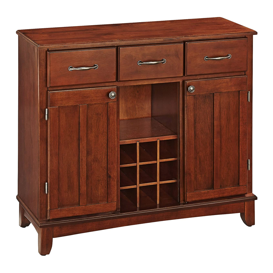
88 5100 001
Buffet with Doors
and Drawers (Natural Finish)
IMPORTANT NOTE
Carefully remove all the parts from the carton and put
them individually on a soft cloth to prevent scratches
or other damages occuring to the wood parts.
We have taken great care in the design of this
product and request that you carefully and strictly
follow our assembly instructions to ensure a
completed product as it was designed.
Buffet Unit Part List
A.
B.
Side Panel
Side Panel
1 pc.
1 pc.
K.
Front Piece
2 pcs.
O.
P.
Wine Grid
Wine Grid
2 pcs.
2 pcs.
Hardware List
Hex Wrench
Head Cap Bolt (long)
1 pc.
8 pcs. (+1 extra)
Head Cap Bolt
4 pcs. (+1 extra)
Tools Required For Assembly : Phillips screwdriver
Home Styles Consumer Assistance Line 888-680-7460 and 877-831-0319
C.
Middle Panel
Middle Panel
1 pc.
1 pc.
L.
Fixed Shelf
1 pc.
Q.
R.
Shelf
Door
2 pcs.
1 pc.
Cam Lock
14 pcs.(+1 extra)
Cross Dowel
Cam Lock Screw
8 pcs.(+1 extra)
14 pcs.(+1 extra)
servicedesk@homestyles-furniture.com
Casual Attire For Today's Home
F.
D.
E.
Back Piece
Back Panel
3 pcs.
2 pcs.
M.
Base
1 pc.
Wood Screw (short)
for Drawer Base Part
12 pcs. (+1 extra)
Wood Screw (long)
for Drawer Side Part
24 pcs. (+1 extra)
G.
Back Stretcher
1 pc.
H.
Back Stretcher
1 pc.
I.
Front Piece
1 pc.
J.
Front Piece
1 pc.
T.
Drawer
3 pcs.
S.
Door
(Knock-Down Construction, please refer to
the last page of these instructions for steps
1 pc.
to complete assembling drawers)
Wood Screw
Machine Screw
for Back Panel
8 pcs.
pcs. (1 extra)
12
Adjustable Pin
8 pcs. (+2 extra)
N.
Leg
2 pcs.
Door
Pull Handle
2 pcs.
Drawer
Pull Handle
3 pcs.
Advertisement

Subscribe to Our Youtube Channel
Related Manuals for Home Styles Buffet with Doors and Drawers


Summary of Contents for Home Styles Buffet with Doors and Drawers
- Page 1 Cam Lock Screw for Drawer Side Part 8 pcs. (+2 extra) 4 pcs. (+1 extra) 8 pcs.(+1 extra) 14 pcs.(+1 extra) 24 pcs. (+1 extra) Tools Required For Assembly : Phillips screwdriver Home Styles Consumer Assistance Line 888-680-7460 and 877-831-0319 servicedesk@homestyles-furniture.com...
- Page 2 Cam Lock Screw for Drawer Side Part 8 pcs. (+2 extra) 4 pcs. (+1 extra) 8 pcs.(+1 extra) 14 pcs.(+1 extra) 24 pcs. (+1 extra) Tools Required For Assembly : Phillips screwdriver Home Styles Consumer Assistance Line 888-680-7460 and 877-831-0319 servicedesk@homestyles-furniture.com...
- Page 3 Cam Lock Screw for Drawer Side Part 8 pcs. (+2 extra) 4 pcs. (+1 extra) 8 pcs.(+1 extra) 14 pcs.(+1 extra) 24 pcs. (+1 extra) Tools Required For Assembly : Phillips screwdriver Home Styles Consumer Assistance Line 888-680-7460 and 877-831-0319 servicedesk@homestyles-furniture.com...
- Page 4 Cam Lock Screw for Drawer Side Part 8 pcs. (+2 extra) 4 pcs. (+1 extra) 8 pcs.(+1 extra) 14 pcs.(+1 extra) 24 pcs. (+1 extra) Tools Required For Assembly : Phillips screwdriver Home Styles Consumer Assistance Line 888-680-7460 and 877-831-0319 servicedesk@homestyles-furniture.com...
- Page 5 Cam Lock Screw for Drawer Side Part 8 pcs. (+2 extra) 4 pcs. (+1 extra) 8 pcs.(+1 extra) 14 pcs.(+1 extra) 24 pcs. (+1 extra) Tools Required For Assembly : Phillips screwdriver Home Styles Consumer Assistance Line 888-680-7460 and 877-831-0319 servicedesk@homestyles-furniture.com...
- Page 6 Cam Lock Screw for Drawer Side Part 8 pcs. (+2 extra) 4 pcs. (+1 extra) 8 pcs.(+1 extra) 14 pcs.(+1 extra) 24 pcs. (+1 extra) Tools Required For Assembly : Phillips screwdriver Home Styles Consumer Assistance Line 888-680-7460 and 877-831-0319 servicedesk@homestyles-furniture.com...
- Page 7 Assembly Instructions 2/5 IMPORTANT Do not tighten up all the screws until each part is properly assembled. You should keep Hex Wrench in the safe place as you may need to tighten up the Head Cap Bolts in the future. Cam Lock Screw STEP 1 Put Cam Lock Screws into the...
- Page 8 Assembly Instructions 3/5 Cam Lock Screw Cam Lock Cross Dowel Head Cap Bolt (long) STEP 3 Attach Middle Panel (C) to the unit with Cross Dowels and Head Cap Bolts (long). Attach Fixed Shelf (L) and Middle Panel (D) to the unit, using Cam Lock Screws, Cam Locks, Cross Dowels and Head Cap Bolts.
- Page 9 Assembly Instructions 4/5 STEP 5 Cam Lock Screw Now, you’ll be able to create your own Buffet and Hutch. Make your own choice of the ‘Top’, wood or stainless steel. Put the Cam Lock Screw into the pre-drilled holes at Top. STEP 6 Turn the unit back to its normal position.
-
Page 10: Part List
Assembly Instructions 5/5 Drawer Using a philips screwdriver, insert 1” screws into the pre-drilled holes as shown, tighten half way. (See figure 1) (Figure 1) MAKE SURE ROLLER IS ON THE BACK Slide the Plywood Base Part (T5) into the grooves on Side Parts (T3) and (T4). Be sure to push the plywood all the way forward so it meets the Front Part (T1).
Need help?
Do you have a question about the Buffet with Doors and Drawers and is the answer not in the manual?
Questions and answers